Core Technical Interpretation
Although the source text is about ROHM’s ESD protection diodes for >10 Gbps interfaces, the engineering relevance to EV battery systems is indirect but important: modern battery packs increasingly rely on high-speed sensing, communication, and camera/ADAS networks for BMS telemetry, isolation monitoring, thermal subsystem control, and powertrain coordination. In that context, ultra-low-capacitance ESD devices matter because they preserve signal integrity on SerDes, MIPI, USB4, PCIe, and automotive camera links that often coexist physically near high-voltage switching environments, contactors, and inverter EMI sources.
The article itself does not describe a battery cell, so any chemistry-specific discussion must be inferred from the EV application domain rather than from the diode product. For a battery teardown engineer, the key point is that the pack-level electronics architecture increasingly influences how safely and accurately a battery is managed under fast charge, high thermal load, and harsh EMC conditions.
Assumed Cell Chemistry and Intrinsic Limitations
Most Likely Chemistry Context: LFP and NMC in Different Duty Cycles
For contemporary EV platforms, the most probable chemistries relevant to the surrounding system are:
- LFP (LiFePO₄) for cost-focused, high-cycle-life, thermally robust platforms
- NMC (LiNiMnCoO₂ or related high-nickel variants) for higher energy density and longer range
- Solid-state as an emerging, not-yet-mainstream architecture with unresolved manufacturability and interface issues
Because the article focuses on high-speed vehicle electronics rather than the cell itself, the likely use case is an EV architecture that could pair:
- LFP in commercial fleets, entry vehicles, or thermal-safety-oriented pack designs
- NMC in premium/high-range vehicles where pack energy density is prioritized
LFP: Structural Strengths and Limits
Intrinsic advantages
- Higher thermal stability than layered oxide cathodes
- Lower oxygen release risk under abuse
- Better cycle life and more tolerant to elevated state-of-charge storage
Intrinsic limitations
- Lower gravimetric and volumetric energy density
- Lower nominal voltage versus NMC
- Poorer low-temperature charge acceptance
- Stronger polarization under high C-rate charging due to lower effective kinetics at cold temperatures
From an engineering standpoint, LFP’s lower thermal runaway propensity does not remove the need for tight electrical integrity. In fact, the pack may be more aggressively fast-charged to compensate for lower energy density, which raises overpotential and lithium plating risk at the anode even if the cathode chemistry is thermally safer.
NMC: Higher Energy Density, Higher Stress Sensitivity
Intrinsic advantages
- Higher cell voltage and energy density
- Better range per mass and per volume
- Better fit for premium EV architectures
Intrinsic limitations
- More exothermic failure pathways than LFP
- Higher sensitivity to overcharge, elevated temperature, and calendar aging
- Greater cathode reactivity at high SOC
- More pronounced degradation from repeated high-rate charging
For NMC, the dominant engineering problem is not only thermal runaway propagation but also the narrower safe operating envelope during fast charge. As nickel content increases, thermal and electrochemical margins decrease. This increases the importance of accurate BMS sensing and robust communication links—precisely the kind of signal paths where low-capacitance ESD devices matter.
Solid-State: Promising but Not a Teardown Reality Yet
If a solid-state pack were considered, the idealized benefits would be:
- Reduced flammable liquid electrolyte
- Potentially higher energy density
- Improved abuse tolerance
However, intrinsic limitations remain:
- High interfacial resistance at electrode/electrolyte boundaries
- Mechanical contact loss under cycling
- Dendrite suppression remains incomplete in practical systems
- Manufacturing yield and stack pressure requirements are still major barriers
Solid-state does not eliminate fast-charge issues; instead, it often relocates them from liquid-electrolyte transport limits to interface impedance, stack pressure management, and localized current density control.
Thermal Management Challenges at the Pack and Module Level
Why This Article Matters to Battery Thermal Design
The article is centered on high-speed electronics integrity, but the broader EV architecture increasingly integrates:
- BMS controllers near the pack
- High-speed serialization/deserialization links to zonal controllers
- Camera and sensor bus systems near thermal hot spots
- Safety interlocks and diagnostics that must remain stable under EMI
These circuits are often mounted in or near battery enclosures, which creates a thermal problem: high-power switching components and pack monitoring electronics must survive in an environment where cells, busbars, contactors, and coolant plates all create spatial temperature nonuniformity.
Liquid Cooling Plate Design: Core Challenges
In a battery module, liquid cooling plates are usually employed to control cell temperature during discharge and especially fast charge. The main engineering constraints are:
1. Spatial Thermal Uniformity
A good plate must minimize:
- Cell-to-cell temperature spread
- Intra-cell axial gradients
- Hot spots near tabs, current collectors, and busbar junctions
Even a few degrees Celsius of gradient can create:
- Unequal aging
- SOC estimation drift
- Current imbalance
- Localized lithium plating during charge
2. Coolant Channel Geometry
Channel design affects:
- Heat transfer coefficient
- Pressure drop
- Maldistribution
- Flow-induced thermal nonuniformity
Narrow channels improve convective heat transfer but increase pressure drop and pump load. Wider channels reduce pumping burden but may create dead zones. Serpentine channels can improve distribution but may induce nonuniform thermal resistance from inlet to outlet.
3. Plate-to-Cell Contact Resistance
The interface stack-up matters enormously:
- Cell can
- Gap pad / thermal interface material
- Cooling plate
- Mounting tolerances
If the thermal interface resistance varies across the module, the center cells may run hotter than edge cells. This is especially problematic in fast-charging packs where core temperature rise can significantly exceed surface measurements.
Thermal Gradients: The Hidden Degradation Driver
The most important thermal parameter in battery packs is not absolute temperature alone, but temperature gradient. High gradients create:
- Nonuniform SEI growth
- Local current density concentration
- Uneven expansion and mechanical stress
- Capacity divergence between parallel cells
For cylindrical formats, the classic issue is radial temperature gradients: the core runs warmer than the shell. For prismatic or pouch cells, the issue is often through-thickness and tab-adjacent gradients. These gradients become severe under high C-rate charging.
Tab Cooling vs. Surface Cooling
Tab Cooling
Tab cooling directly targets the region where current enters/exits the cell.
Advantages
- Reduces resistive heating near current collector junctions
- Helps control local hot spots
- Can reduce current crowding near the tab weld region
Limitations
- Does not uniformly cool the electrochemically active area
- Can create a thermal gradient if the tab is much colder than the cell body
- Adds mechanical and packaging complexity
- Difficult to scale uniformly across densely packed modules
Surface Cooling
Surface cooling couples the cooling plate to the broad face of the cell.
Advantages
- Better average heat removal
- Easier module integration
- More uniform across prismatic/pouch cell face area
Limitations
- Core-to-surface thermal resistance remains significant
- Heat generated deep in the jelly roll or laminate stack may be removed too slowly
- The tab region may still be a localized hot spot
Engineering Tradeoff
The optimal approach is often a hybrid thermal architecture:
- Surface cooling for bulk heat removal
- Localized tab/busbar thermal management
- Predictive control of charge current based on cell temperature mapping
This is where robust signal integrity becomes indirectly relevant: temperature sensors, isolated comms, and high-speed control links must remain accurate and artifact-free even near high-voltage switching and thermal transients.
Fast-Charging Constraints
Why Fast Charging Is Fundamentally Limited by Electrochemistry
Regardless of whether the pack uses LFP or NMC, fast charging is constrained by three coupled transport phenomena:
- Li-ion diffusion in the solid active material
- Ionic transport through the electrolyte
- Charge transfer kinetics at the electrode/electrolyte interface
At high C-rates, the applied current demands can exceed the cell’s ability to redistribute lithium uniformly. That produces concentration gradients, polarization, heat generation, and eventual degradation.
Ionic Conductivity and Electrolyte Transport Limits
The electrolyte must transport lithiation species from cathode to anode during charging. At high current:
- Local ion depletion can occur near the separator/electrode interface
- Concentration polarization increases
- Ohmic losses rise
- Temperature rises, which may temporarily improve conductivity but also accelerate aging
This creates a non-linear charging envelope:
- At moderate temperature, charge acceptance is acceptable
- At low temperature, ionic mobility drops significantly
- At high SOC, anode potential approaches the lithium plating threshold
Lithium Plating Risk at High C-Rates
Lithium plating occurs when intercalation into graphite cannot keep pace with incoming Li flux and metallic lithium deposits on the anode surface.
Conditions that promote plating
- Low temperature
- High charge current
- High SOC
- Elevated cell impedance
- Nonuniform current density
- Poor thermal uniformity across the module
Consequences
- Loss of cyclable lithium
- Increased impedance
- Dendritic growth risk
- Accelerated capacity fade
- Potential internal short during later cycles
Chemistry-Specific Fast-Charge Behavior
LFP
LFP can tolerate abuse thermally better than NMC, but fast charging is still constrained by:
- Graphite anode kinetics
- Low-temperature performance
- Voltage plateau behavior that complicates SOC estimation
Because the voltage curve is flatter, the BMS often has less headroom to infer early onset plating using voltage alone.
NMC
NMC packs often have:
- Higher energy density
- Better nominal range
- More acute sensitivity to overpotential and heat
Fast charging in NMC creates stronger pressure on thermal design and balancing accuracy, especially at high SOC when the anode is nearing its lithiation limit.
Solid-State
Solid-state architectures are often marketed as enabling faster charge, but practical limits emerge from:
- High interfacial impedance
- Contact resistance growth
- Stack pressure dependence
- Nonuniform current distribution leading to local hot spots
So the promise of faster charging is not automatically realized unless the interface engineering is solved.
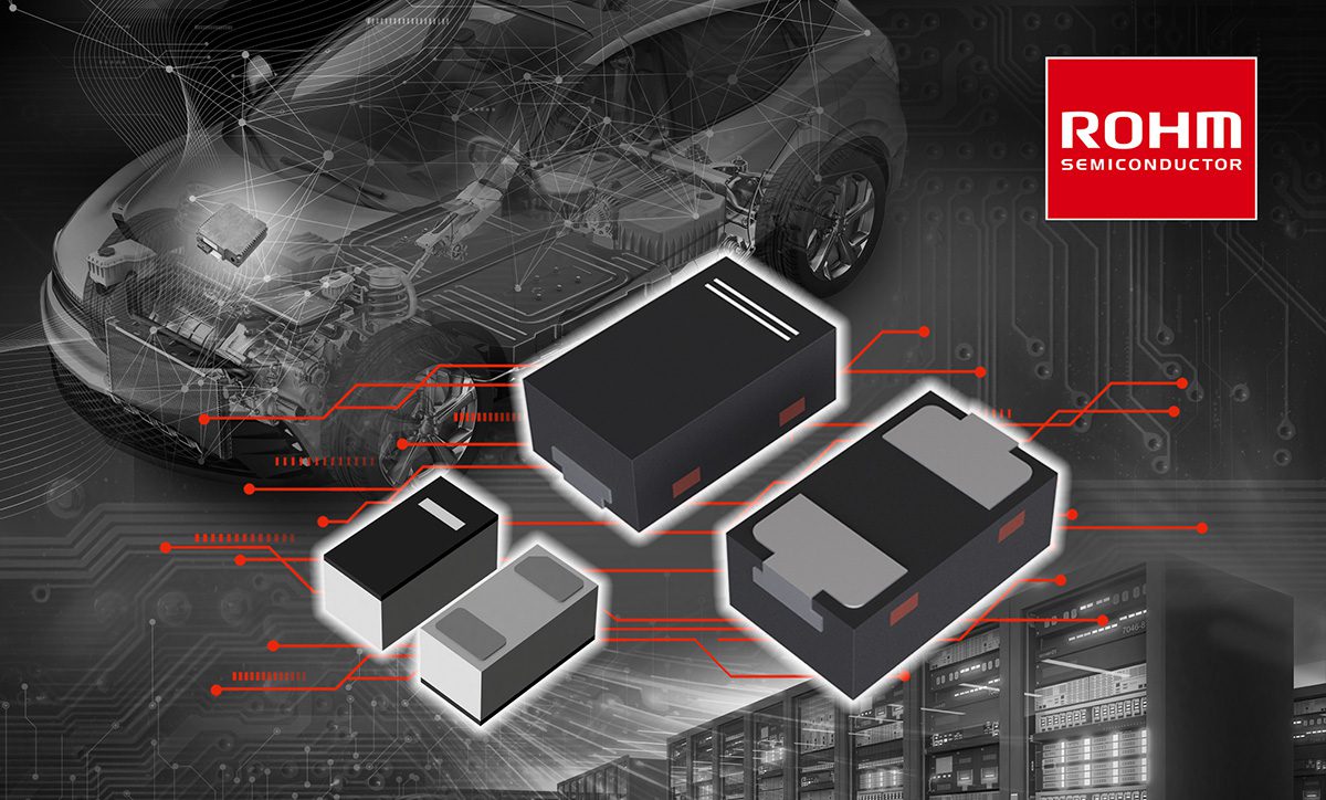
Why Low-Capacitance ESD Protection Matters in EV Battery Electronics
Signal Integrity in Battery-Adjacent High-Speed Networks
The article’s core technical point is the maintenance of signal integrity above 10 Gbps with extremely low parasitics:
- 0.24 pF bidirectional capacitance
- 0.48 pF unidirectional capacitance
- 0.28 Ω dynamic resistance
In EV battery systems, high-speed links may support:
- BMS-to-domain-controller data transport
- Camera and sensor data near battery thermal systems
- Diagnostic and monitoring links for zonal architectures
At these speeds, parasitic capacitance can:
- Add insertion loss
- Red shape edges
- Increase deterministic jitter
- Disturb differential impedance
- Compromise eye opening
Relevance to Battery Engineering
From a teardown perspective, this matters because better ESD protection enables:
- More reliable temperature sensing
- Higher-fidelity pack telemetry
- Robust isolated communications under EMI
- Improved diagnostic accuracy during fast charge and thermal stress
That does not change cell chemistry, but it does improve the control system that determines whether the cell is operated safely within its electrochemical and thermal limits.
Engineering Bottom Line
Primary Cell-Level Constraints
- LFP: thermally safer, but lower energy density and limited low-temperature fast-charge capability
- NMC: higher energy density, but lower abuse tolerance and tighter thermal management requirements
- Solid-state: promising, but still dominated by interfacial and manufacturability constraints
Primary Thermal Constraints
- Battery safety depends on controlling thermal gradients, not just average pack temperature
- Liquid cooling plate design must balance heat transfer, pressure drop, and module uniformity
- Tab cooling and surface cooling solve different parts of the thermal problem and are often complementary
Primary Fast-Charge Constraints
- Fast charging is limited by ionic conductivity, diffusion, and reaction kinetics
- Lithium plating becomes a dominant risk at high C-rate, low temperature, and high SOC
- BMS accuracy and high-speed communications are essential to enforcing safe charge envelopes
Practical Conclusion
The article’s real engineering significance for EV battery professionals is that as pack-level electronics become faster and more networked, electrical robustness must match electrochemical complexity. Ultra-low-capacitance ESD devices are not a battery-cell innovation, but they are part of the control-layer infrastructure that enables safer fast charging, better thermal management, and more reliable operation in high-energy EV packs.