Technical Interpretation of the PowerSled Platform
PowerSled is best interpreted as a mobile battery energy storage system (BESS) integrated into a towable trailer architecture, with auxiliary propulsion assist, off-grid power export, and optional solar integration. From an EV battery engineering perspective, the article implies a system that must satisfy three competing requirements simultaneously:
- High energy density
- High power delivery for propulsion assist and V2L
- High reliability under mobile, outdoor, and potentially harsh thermal/mechanical duty cycles
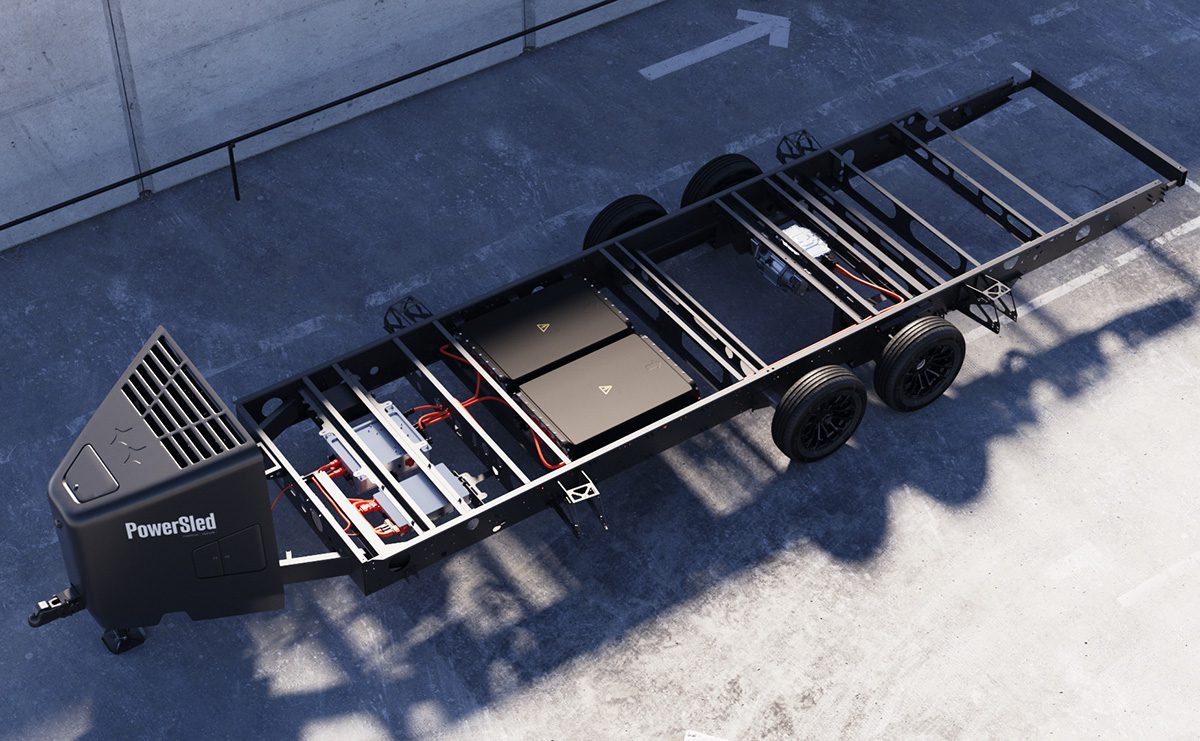
The platform’s stated 80 / 160 / 240 kWh battery options and 38 kW V2L output make chemistry selection, thermal design, and charge acceptance critical. The article does not disclose the cell chemistry, so the analysis below treats the chemistry as an engineering inference rather than a fact.
1) Assumed Cell Chemistry and Intrinsic Limits
Most likely chemistry: LFP, possibly pack-level optimized for durability
For a commercial mobile power trailer, the most probable chemistry is LFP (LiFePO4) or an LFP-dominant variant. The reasons are structural and economic:
- High cycle life
- Superior thermal stability
- Lower cost per kWh
- Reduced propagation risk compared with high-nickel NMC
- More tolerant of long dwell in partial state of charge
- Better fit for stationary/mobile BESS duty than energy-dense automotive range packs
In a towable platform that may sit idle, support tools, and repeatedly cycle between AC charging, DC fast charging, and V2L discharge, LFP is often the most rational engineering choice.
Why not NMC as the primary assumption?
NMC would offer higher gravimetric and volumetric energy density, which matters if trailer mass and packaging volume are constrained. However, NMC is less attractive here because:
- Lower thermal runaway onset margin
- Higher sensitivity to calendar aging at elevated SOC and temperature
- More demanding cell-to-cell balancing and thermal uniformity requirements
- Higher risk under repeated high-power discharge and fast charging
- More expensive BOM and protection burden
If the product is optimized for field robustness rather than maximum range, LFP is the more plausible choice.
Why solid-state is unlikely
A solid-state pack would be attractive from a safety and energy-density standpoint, but the article describes a near-term commercial platform with NACS charging, multiple pack sizes, and field deployment. That strongly suggests a conventional lithium-ion architecture rather than a production solid-state system. Solid-state would also introduce unresolved integration issues:
- Interface resistance sensitivity
- Stack pressure requirements
- Lower practical power capability in many implementations
- Manufacturing immaturity and scaling risk
- Thermomechanical brittleness under trailer vibration and shock
So the most defensible inference is LFP prismatic cells or modules, possibly with a conventional liquid-cooled pack and automotive BMS.
2) Intrinsic Limitations of the Likely Chemistry
If LFP is used
LFP’s strengths come with well-known limitations:
-
Lower cell voltage plateau (~3.2 V nominal)
This increases series count for a given pack voltage and complicates module balancing. -
Lower energy density than NMC
For a 240 kWh pack, mass and volume become significant, especially in a trailer that must still carry payload. -
Flat OCV-SOC curve
This makes SOC estimation more difficult because voltage is a poor proxy over much of the usable window. -
Cold-temperature performance penalty
Internal resistance rises sharply at low temperature, reducing charge acceptance and increasing lithium plating risk during fast charge if not preconditioned. - Reduced high-rate charge acceptance relative to power-optimized chemistries
Although LFP is robust, it still cannot violate diffusion and intercalation kinetics.
If NMC were used instead
The main limitations are different:
- Higher cathode instability at high SOC and high temperature
- More severe calendar aging
- Greater gas generation risk
- Stricter thermal management requirement
- Tighter fast-charge envelope
- Greater risk of thermal runaway propagation
For a vehicle-adjacent trailer expected to operate near workers and equipment, those tradeoffs are nontrivial.
3) Battery Pack Architecture Implications
Pack sizing and power ratio
At 80, 160, and 240 kWh, the platform may span very different C-rate regimes depending on load. The stated 38 kW V2L output corresponds to approximate continuous discharge rates of:
- 0.48C on 80 kWh
- 0.24C on 160 kWh
- 0.16C on 240 kWh
These are moderate continuous rates, but the propulsion-assist function introduces additional transient stress. The 40 hp continuous / 94 hp peak motor output equals approximately:
- 30 kW continuous
- 70 kW peak
If battery power is shared between traction assist and export loads, the system may be asked to deliver 50–100 kW-class bursts depending on duty cycle and operating voltage. That pushes the design into a regime where DC bus resistance, contactor heating, cell impedance rise, and thermal stripe nonuniformity become dominant issues.
Mechanical design constraints
Because the battery is in a trailer, not an underbody enclosure, the pack must tolerate:
- Vertical shock from road inputs
- Trailer yaw-induced torsion
- Connector fretting
- Vibration-induced weld and busbar fatigue
- Ingress, dust, water spray, and thermal cycling
- Long-duration solar heat soak
- Potential curb/field impacts
These are not minor issues. A trailer battery pack sees a different mechanical spectrum than a passenger EV pack. Module fixation, cell compression strategy, and busbar strain relief matter as much as electrochemistry.
4) Thermal Management Challenges
4.1 Liquid cooling plate design
A pack of this size almost certainly requires active liquid thermal management if it is expected to support DC fast charging and high-power V2L. The common architecture would be:
- Cell groups mounted to aluminum or composite module structures
- Cold plates beneath or adjacent to module bases
- Glycol-water coolant loop with pump, radiator, and possibly chiller interface during DCFC
- BMS-controlled thermal preconditioning
Key engineering constraints
The cold plate must balance:
- Low thermal resistance
- Uniform surface temperature distribution
- Acceptable pressure drop
- Manufacturability and serviceability
- Corrosion resistance and coolant compatibility
A major issue is thermal gradient management across long trailer pack geometries. If the pack is distributed over a large underframe footprint, cells near coolant inlet zones can operate cooler than downstream cells. This can create:
- SOC imbalance acceleration
- Unequal aging
- Localized charge-current limiting
- Reduced usable pack capacity
Cold plate topology
Technically, the most relevant designs are:
- Serpentine channels: high heat transfer, but high pressure drop and inlet-to-outlet temperature rise
- Parallel microchannels: better uniformity, but distribution maldistribution risk
- Embedded manifold plates: improved zonal control, higher manufacturing complexity
- Direct-to-module cooling: compact, but demands very flat mating surfaces and low interface resistance
For a commercial mobile platform, the likely tradeoff is cost versus thermal uniformity. If cost is controlled too aggressively, the pack may experience hotspot formation at the cell center and near tabs, especially during DCFC and sustained export loads.
4.2 Thermal gradients across the pack
Why gradients matter
Battery aging is strongly temperature dependent. Even modest gradients can produce large lifetime differences. For example:
- Cells operating 8–12°C hotter can age materially faster
- Hotter cells generally show higher self-discharge and impedance growth
- During charging, warmer cells may reach voltage limits earlier, forcing pack derating
In a trailer BESS, gradients can arise from:
- Coolant inlet/outlet delta-T
- Unequal solar loading on enclosure surfaces
- Airflow asymmetry from towing
- Localized inverter or contactor heat sources
- Uneven cell stacking and compression
Expected failure mode
The most likely system-level penalty is not immediate failure, but progressive pack imbalance and growing power derate. The BMS may need to limit charge current based on the hottest cell, meaning a small thermal bottleneck can reduce full-pack capability.
4.3 Tab cooling versus surface cooling
Surface cooling limits
Surface cooling works well for pack-level heat removal when cells have broad contact with a cold plate, but it has intrinsic limits during high-rate conditions:
- Heat generated inside the jelly roll or prismatic stack must conduct to the surface
- The center of thick cells can remain significantly hotter than the outer skin
- Large-format cells have reduced effective through-thickness thermal diffusivity
- Surface cooling cannot directly address local tab hotspots
Tab heating as a thermal bottleneck
At high current, tabs and weld regions generate nontrivial resistive losses:
- ( P = I^2R ) rises quickly with current
- Local resistances at welds, busbars, and termination points can dominate
- Tab temperature may exceed the bulk cell temperature even if the cell envelope is well cooled
Tab cooling advantages and disadvantages
Advantages
- Directly addresses localized ohmic heating
- Reduces hotspot formation at current collection points
- Can improve fast-charge robustness and discharge durability
Disadvantages
- Adds assembly complexity
- Increases risk of mechanical stress concentration
- Harder to seal and maintain
- Requires excellent thermal coupling without compromising electrical isolation
For a mobile trailer pack, the ideal design may combine:
- Cell-body cooling for baseline heat extraction
- Enhanced thermal paths near current collectors
- Zonal coolant routing
- Strict current distribution control
If the pack relies only on surface cooling, the tabs may become the performance-limit component, especially during fast charge or sustained 38 kW V2L discharge.
5) Fast-Charging Constraints
5.1 Ionic conductivity limits
Fast charging is not simply a matter of supplying more power. Cell acceptance is bounded by:
- Lithium-ion diffusion through the electrolyte
- Solid-state diffusion within the active material
- Charge-transfer kinetics at the electrode/electrolyte interface
- Ohmic losses in current collectors, tabs, and busbars
At higher C-rates, polarization increases. The practical consequence is that cell terminal voltage rises faster than the bulk state of lithiation allows, meaning the charger must taper current earlier than nominal.
LFP-specific implications
LFP generally has:
- Lower nominal voltage
- Good cycle life
- Moderate power capability
- But limited fast-charge tolerance when cold or near full SOC
Its flat voltage profile can be advantageous for usable energy delivery, but it complicates precise charge control and makes end-of-charge taper particularly important.
5.2 Lithium plating risk
Lithium plating is one of the key hard constraints in fast charging, especially under the following conditions:
- Low temperature
- High SOC
- High charge current
- Elevated cell impedance
- Nonuniform cell heating
- Inadequate preconditioning
Mechanism
When the anode potential falls too low versus Li/Li+, lithium ions cannot intercalate fast enough into graphite or graphite-composite anodes. Metallic lithium then deposits on the anode surface. This causes:
- Capacity loss
- Impedance growth
- Potential dendritic growth
- Safety risk under repeated cycling
Why trailer use is challenging
A trailer may arrive cold-soaked on a job site, then be asked to fast charge or immediately support load. Without active preheating, the pack can be outside its safe charge envelope. This is especially problematic because trailer duty cycles are operationally variable; the system cannot assume stable garage-like ambient conditions.
5.3 DC fast charging via NACS
The presence of an NACS connector with DC fast charging support implies a charge-control system capable of negotiating:
- Current limits based on cell temperature
- Pack voltage limits
- Thermal preconditioning
- Contactor sequencing
- Isolation monitoring
- Fault detection at the vehicle-side or trailer-side module level
For a large-energy trailer pack, DC charging may be constrained more by:
- Thermal rejection capability
- Cell acceptance
- Connector and harness current rating
- Pack voltage architecture
- BMS conservative derating
than by the nominal charger power alone.
6) System-Level Engineering Tradeoffs
6.1 Why the use case stresses the battery
PowerSled is not just a battery pack; it is simultaneously:
- A mobile energy storage asset
- A propulsion-assist module
- A jobsite generator replacement
- A towing-efficiency augmenter
- A potentially solar-supported field power node
That combination produces conflicting requirements:
- Long-life chemistry favors conservative C-rates
- Fast deployment favors high charge acceptance
- Mobility favors low mass
- High autonomy favors high kWh
- Safety favors robust thermal margins
- Harsh field use favors mechanically simple packaging
6.2 Most likely design philosophy
The most plausible engineering strategy is:
- LFP cells for safety and cycle life
- Liquid cooling for charge/discharge thermal control
- Moderate C-rate operation with aggressive derating at temperature extremes
- Pack segmentation into multiple modules/zones
- BMS-based current limiting to prevent plating and hotspot formation
- Potentially conservative charging curves relative to passenger EVs
7) Engineering Assessment
From a battery-teardown and systems perspective, the PowerSled concept suggests a durable, moderately high-power LFP-based mobile BESS rather than a high-energy-density EV traction pack. The real technical challenge is not just storing energy, but doing so in a trailer envelope that experiences:
- High mechanical shock
- Unstable ambient temperature
- Variable discharge profiles
- DC fast charging
- Continuous auxiliary power export
The core validation questions for such a product would be:
- What is the actual cell chemistry and form factor?
- How is module thermal uniformity maintained across the trailer length?
- Can the pack fast charge without lithium plating in cold-soak conditions?
- Are tabs, busbars, and connectors thermally overdesigned for sustained high-current output?
- Does the BMS control strategy prevent localized aging from becoming pack-limiting?
If the platform is indeed LFP, its success will depend less on chemistry novelty and more on thermal architecture, charge-control calibration, and mechanical durability. In this application, those implementation details will determine field reliability more than nominal kWh rating.