Technical Analysis of the eActros Lowliner Battery and Powertrain Architecture
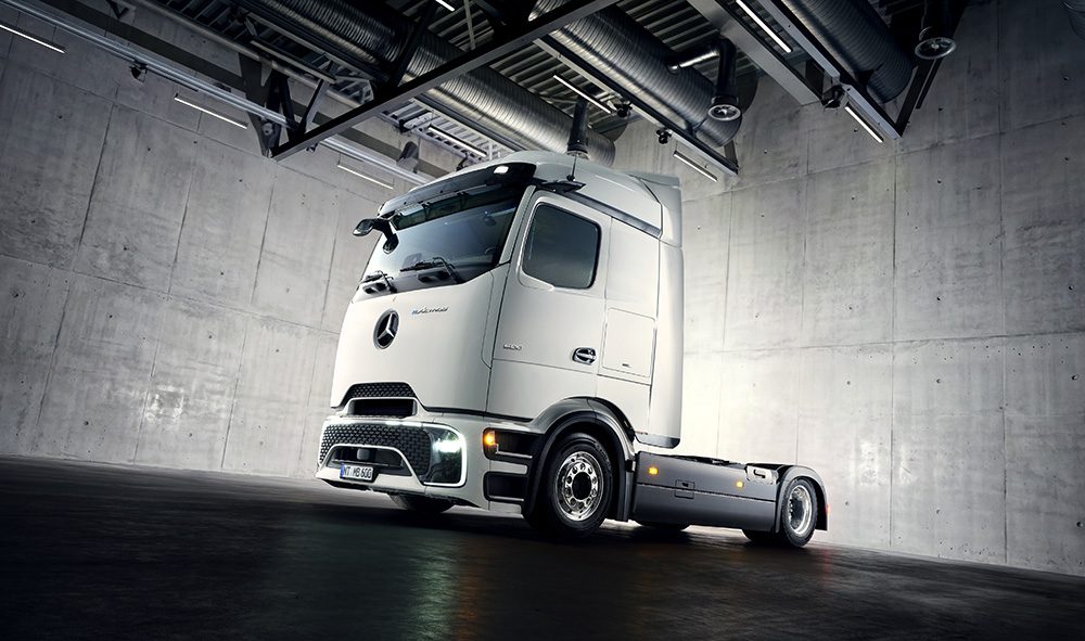
The article describes a configuration of Mercedes-Benz Trucks’ eActros Lowliner that is materially relevant to battery engineers because it combines a high-voltage 800 V architecture, LFP battery packs, and fast-charging capability up to 400 kW with future MCS support in a heavy-duty long-haul platform. From an engineering standpoint, this implies optimization around energy throughput, thermal robustness, packaging efficiency, and cycle life rather than maximum gravimetric energy density.
Assumed Cell Chemistry: LFP and Its Design Tradeoffs
The article explicitly states that the vehicle uses LFP battery packs. In a heavy-duty truck application, this is a technically coherent choice because LFP typically offers:
- higher thermal stability than layered oxide chemistries,
- long cycle life under deep cycling,
- lower cost and supply-chain risk due to no nickel/cobalt dependence,
- improved resistance to thermal runaway propagation relative to NMC.
However, LFP has intrinsic limitations that shape the entire vehicle architecture.
Intrinsic Limitations of LFP
Lower energy density
Compared with NMC, LFP has lower specific and volumetric energy density. For a truck platform, this means:
- larger pack volume for equivalent range,
- increased pack mass penalty,
- reduced payload if more packs are added.
This is directly reflected in the article: the two-pack 414 kWh configuration yields higher payload, while the three-pack 621 kWh configuration trades payload for range.
Flat voltage plateau
LFP cells exhibit a relatively flat open-circuit voltage curve over much of the SOC window. This complicates:
- SOC estimation based on voltage inference,
- balancing algorithms,
- end-of-charge detection,
- digital twin calibration for fleet energy management.
In fleet applications, precise coulomb counting and adaptive model-based SOC estimation become more important than voltage-based heuristics.
Low-temperature performance
LFP suffers from reduced low-temperature power capability due to:
- decreased ionic conductivity in electrolyte at low temperature,
- slower solid-state diffusion in the olivine structure,
- increased charge-transfer impedance,
- higher risk of lithium plating during charging.
This is especially relevant for fast charging, because a truck charged after highway operation in winter may have cell temperatures outside the ideal charging window.
Power capability constraints at high SOC and low temperature
Although LFP can provide robust discharge power, charging power is typically more constrained than discharge power because the anode becomes more vulnerable to plating when:
- temperature is low,
- SOC is high,
- charge current is high,
- internal resistance increases.
That limits how aggressively the pack can absorb 400 kW continuously without a tightly managed thermal and charging envelope.
Thermal Management: System-Level Challenges in a Heavy-Duty 800 V Pack
An 800 V platform reduces current for a given power level, which lowers resistive losses in conductors and busbars. That helps at 400 kW charging and during traction load transients. But the battery thermal problem is not solved by voltage alone; it is shifted into cell-to-cell and module-to-module thermal uniformity.
Why 800 V Matters Thermally
At 400 kW:
- 400 kW / 800 V = 500 A nominal pack current.
That is a manageable current compared with 400 V systems, but still substantial for:
- contactor sizing,
- fuse coordination,
- busbar copper mass,
- terminal heating,
- connector thermal rise during fast charging.
At the cell level, the dominant issue is still heat generation:
- ohmic heat: ( I^2R ),
- entropic heat at certain SOC regions,
- localized heating at tabs/interconnects,
- cooling asymmetry across the pack.
Liquid Cooling Plate Design Considerations
For LFP packs in long-haul trucks, liquid cooling is the practical solution. The device likely uses a cold plate or channel-based liquid thermal interface under or adjacent to the module stack.
Key engineering constraints
-
Thermal contact resistance
- Any gap between cell/module and cooling interface creates a bottleneck.
- TIM selection, compression retention, and aging are critical.
-
Pressure drop vs. heat transfer
- Narrow channels improve heat transfer coefficient but raise pressure drop.
- Higher pressure drop increases parasitic pump power and complicates redundancy.
-
Uniform coolant distribution
- Large packs suffer from inlet-outlet temperature rise.
- The last module in the loop may see a hotter coolant and hence higher cell temperature.
-
Coolant manifold architecture
- In a large-format truck pack, parallel/series coolant routing must prevent thermal shadowing.
- Poor manifold balance leads to thermal hotspots and module-to-module imbalance.
- Freeze, corrosion, and dielectric isolation
- Heavy-duty fleets require robustness across climate zones.
- High-voltage isolation and leak detection become crucial validation items.
Thermal Gradients and Their Consequences
Thermal gradients are one of the most important degradation accelerators in high-capacity pack design.
Within-module gradients
If cells in the same module differ by several degrees Celsius:
- impedance diverges,
- balancing load increases,
- aging disperses across the module,
- SOC window utilization becomes nonuniform.
Pack-level gradients
If one side of the pack is closer to the thermal sink or coolant inlet:
- the “hot end” ages faster,
- usable capacity is limited by the warmest cells,
- charging is curtailed to protect the most stressed cells.
Why this matters more in LFP
LFP generally tolerates heat better than NMC in safety terms, but thermal uniformity still affects:
- cycle life,
- charge acceptance,
- pack balancing,
- power derating thresholds.
Tab Cooling vs. Surface Cooling
This is a critical engineering distinction for high-power fast-charged packs.
Surface cooling
Most common in commercial packs:
- coolant removes heat through a cell’s broad face,
- good for prismatic or pouch cells,
- relatively scalable for module design.
Advantages:
- proven manufacturability,
- simpler sealing,
- good average heat extraction.
Limitations:
- heat generated at the current collectors may not be removed quickly enough,
- thermal path from jelly roll to casing can limit transient response,
- center-to-surface temperature differential can persist during fast charging.
Tab cooling
More relevant when current concentration at terminals becomes a bottleneck.
Advantages:
- directly targets the hottest electrical regions,
- can reduce localized terminal hot spots during high current charge/discharge,
- useful when tabs/interconnects are limiting.
Limitations:
- implementation complexity,
- sealing and insulation challenges,
- limited benefit if bulk cell thickness remains the dominant thermal resistance.
Practical inference for this truck
Given the application and cell chemistry, Mercedes is likely optimizing for surface-cooled prismatic LFP modules with careful attention to terminal/interconnect thermal management, rather than exotic tab-cooled cell structures. At 400 kW charging, however, the terminal region and busbar interconnects still require explicit thermal validation because pack current is high even if voltage helps.
Fast-Charging Constraints: Electrical and Electrochemical Limits
The article states:
- up to 400 kW CCS2 charging
- future MCS capability
From a battery engineering perspective, this is not primarily an inverter or connector problem; it is a cell acceptance and degradation problem.
C-Rate Translation
For the two-pack configuration:
- 414 kWh / 400 kW ≈ 0.97 C pack-level charge power relative to energy.
That is near 1C at the pack level, but not all power can be translated directly into favorable cell charging conditions because:
- pack-to-cell voltage conversion is not trivial,
- charge acceptance is limited by temperature and SOC,
- thermal gradients force conservative BMS limits,
- current distribution inside parallel groups may be nonuniform.
For the three-pack system:
- 621 kWh / 400 kW ≈ 0.64 C.
That lower effective C-rate helps charging, but only if charging is maintained over a sufficiently large SOC window and if thermal conditioning is effective.
Ionic Conductivity Limits
Charging speed is constrained by ionic transport in the electrolyte and solid-phase diffusion in the electrodes.
Electrolyte transport
At higher current:
- Li+ concentration gradients form in the electrolyte,
- ohmic drop increases,
- local overpotential rises,
- anode potential may approach the lithium plating threshold.
Solid-state diffusion in LFP
LFP has a two-phase intercalation mechanism with relatively constrained diffusion kinetics compared with some graphite/LFP pairings in fast-charge regimes. The practical result is:
- increasing polarization at high current,
- reduced usable charge acceptance,
- stronger need for temperature conditioning.
Lithium Plating Risk
The principal degradation risk during fast charging is lithium plating on the graphite anode.
Conditions increasing plating risk
- low cell temperature,
- high SOC,
- high charge current,
- insufficient rest after discharge,
- high internal resistance,
- uneven current distribution.
Why this matters in truck duty cycles
Long-haul trucks may arrive at a charger after:
- sustained high-load operation,
- elevated cell temperatures in some regions of the pack,
- potentially uneven cooling across the pack.
If the pack is then charged aggressively without uniform thermal conditioning, some cells may be too cold while others are hot, creating a situation where the BMS must choose between: - limiting charge power,
- accepting accelerated degradation,
- or increasing preconditioning time.
MCS Implications
Megawatt charging will intensify all of these issues:
- higher current density at connectors,
- more severe busbar and contact heating,
- larger thermal gradients in the pack,
- greater demand on coolant loop capacity,
- stricter limits on cell acceptability at low temperature.
For MCS to be viable, the pack must be designed around:
- high-conductivity in-cell architecture,
- aggressive cooling of module interfaces,
- low-resistance interconnects,
- preconditioning strategy tied to route planning,
- BMS algorithms that constrain current dynamically by cell temperature and inferred lithium plating risk.
Pack Architecture and Vehicle-Level Tradeoffs
The article’s payload note is not incidental—it reveals the engineering priority stack.
Two-pack vs. three-pack configuration
- Two-pack version: lower mass, higher payload, lower energy reserve.
- Three-pack version: higher range, lower payload, more thermal mass, more cooling burden.
This is a classic commercial vehicle optimization problem where:
- energy density,
- payload legality,
- axle loading,
- charge window,
- and route duty cycle
must be balanced.
For eActros Lowliner, the available volume under the low-coupling tractor layout is being exploited to support mega-trailer use without violating overall height constraints. That means the battery system must be packaged with minimal intrusion into chassis geometry while preserving serviceability and crash structure.
Engineering Takeaways
What the article implies technologically
The platform is best understood as a heavy-duty LFP-based 800 V battery-electric truck optimized for long-haul cycle life and payload-sensitive deployment, not as an energy-density-maximized system.
Core engineering constraints
- LFP chemistry favors safety and lifecycle durability, but penalizes energy density and cold-charge performance.
- Liquid cooling design must manage strong thermal gradients in a large pack, especially under fast charging.
- Heat extraction at tabs/interconnects becomes increasingly relevant as charging power approaches truck fast-charge limits.
- Fast charging is limited by ionic transport, low-temperature kinetics, and lithium plating risk.
- MCS readiness will require not only higher-power hardware but a tightly integrated thermal preconditioning and BMS control strategy.
Bottom Line
From a battery engineer’s perspective, the eActros Lowliner is not primarily a chemistry breakthrough; it is a system engineering exercise in making LFP viable for heavy-duty long-haul service under high-voltage, high-power charging constraints. The success of such a platform depends less on nominal pack capacity than on how effectively Mercedes manages thermal uniformity, charge acceptance, and degradation control across a very large, very heavy, commercially utilized battery system.