Core Technology Relevance to EV Battery Engineering
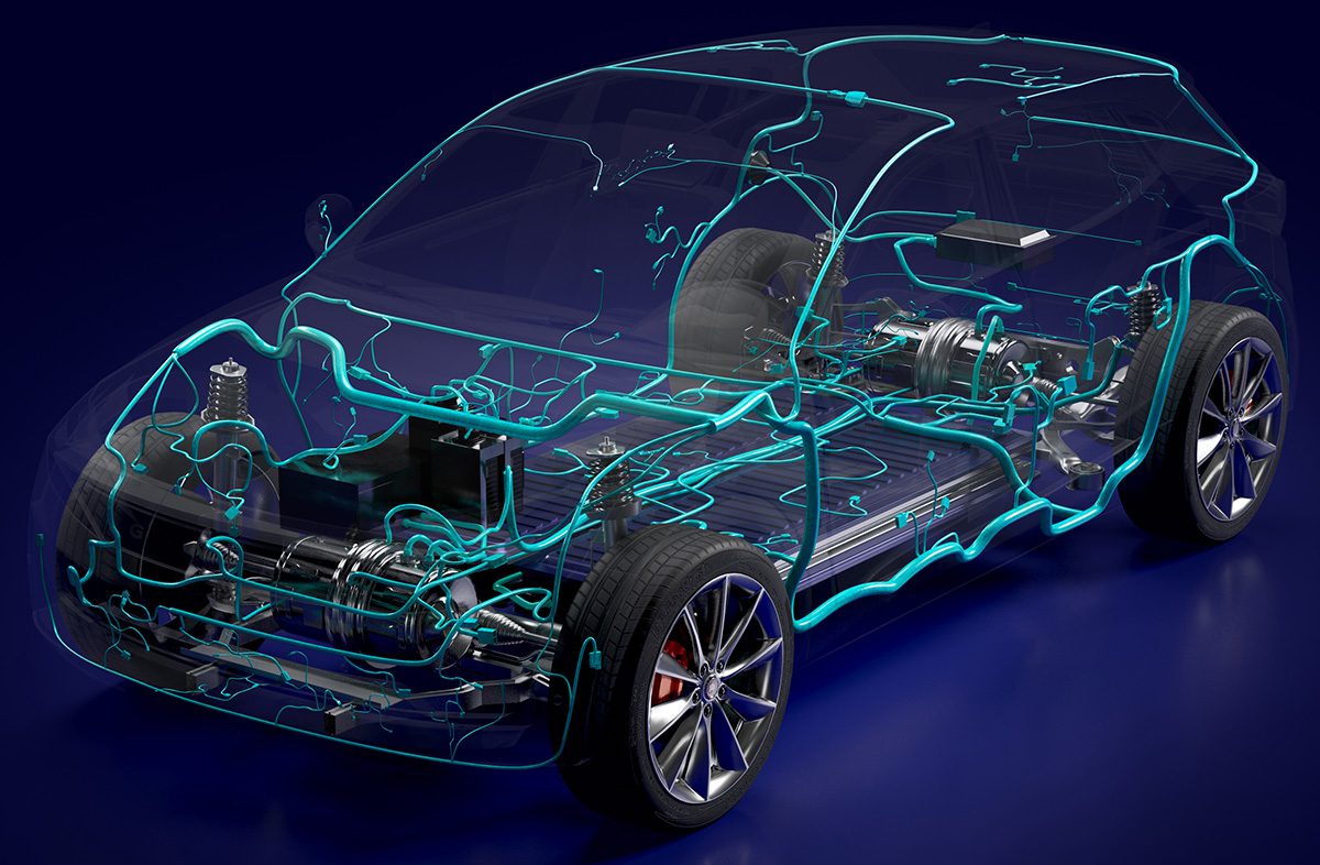
Although the article is primarily about Siemens’ integration of Capital, Designcenter, and Teamcenter for wiring harness development, the underlying engineering problem is highly relevant to EV battery packs: co-design of electrical routing, mechanical packaging, and thermal/mechanical constraints in a 3D digital thread.
For battery systems, the same class of workflow is required for:
- Cell-to-module and module-to-pack interconnect design
- Busbar and high-voltage harness routing
- Cooling plate and coolant manifold packaging
- Service disconnects, contactors, pyro-fuses, sensing lines, and HVIL routing
- Mechanical clearance, vibration robustness, and manufacturability validation
In battery development, late discovery of a routing conflict is not merely a CAD issue—it can directly alter:
- electrical resistance and current density,
- weldability and join quality,
- thermal uniformity,
- pack volumetric efficiency,
- safety margin under crash and fault conditions.
The core technical value of the described workflow is therefore concurrent electro-mechanical-thermal integration in a single authoritative model, which is essential for modern EV battery architecture.
Assumed Cell Chemistry and Intrinsic Limitations
Because the article does not specify chemistry, the most defensible assumption for an EV battery engineer is that the harness/pack workflow is being applied to a liquid-cooled lithium-ion traction pack, most likely LFP or high-নিকel NMC, with solid-state remaining a future-state outlier.
Likely Chemistry: LFP vs. NMC
LFP (Lithium Iron Phosphate)
LFP is increasingly common in mainstream EV packs because of:
- lower cost,
- strong thermal stability,
- long cycle life,
- reduced dependence on nickel and cobalt.
However, its intrinsic limitations are important:
- lower gravimetric and volumetric energy density than NMC,
- higher pack mass and volume for equivalent range,
- flatter OCV-SOC curve, which complicates state estimation,
- reduced low-temperature power and charge acceptance due to poorer ionic and kinetic performance at cold temperatures.
From a packaging standpoint, LFP’s lower energy density drives larger pack footprints, increasing:
- harness length,
- busbar resistance,
- cooling circuit complexity,
- pressure drop and coolant distribution challenges,
- structural stiffness requirements.
NMC (Nickel Manganese Cobalt)
NMC chemistries, especially high-nickel variants, are favored where energy density is prioritized.
Intrinsic limitations include:
- lower thermal stability than LFP,
- higher exothermic oxygen release risk at elevated temperature/state of charge,
- greater sensitivity to overcharge and elevated-rate lithium plating,
- accelerated aging under high temperature and high SOC dwell.
For NMC packs, the routing and cooling integration problem becomes more severe because thermal failure limits are tighter. Harness and busbar layouts must support:
- lower resistance to reduce I²R heating,
- tighter thermal sensing placement,
- shorter interconnect paths,
- more aggressive liquid cooling topology.
Solid-State: Why It Is Unlikely as the Implicit Assumption
A true solid-state pack would change the engineering emphasis substantially:
- reduced flammability risk,
- potentially higher energy density,
- potentially wider thermal operating window.
But intrinsic limitations remain:
- interfacial impedance at solid-solid boundaries,
- stack pressure dependence,
- dendritic or filamentary shorting modes depending on chemistry,
- immature manufacturing yields and scalability.
Since the article focuses on wiring/harness integration rather than cell-electrolyte architecture, the implied context is overwhelmingly a conventional lithium-ion pack, not a solid-state system.
Thermal Management Challenges in the Underlying Battery System
The 3D co-design concept is especially relevant to thermal management, because pack performance is often limited not by nominal cell capacity but by spatial temperature gradients and local hot spots created by geometry constraints.
Liquid Cooling Plate Design Constraints
A battery pack cooling plate is not simply a heat sink; it is a coupled thermal-hydraulic-mechanical component.
Key design concerns include:
- Contact thermal resistance between cell/module base and coolant plate
- Flow maldistribution across parallel channels
- Pressure drop vs. heat transfer coefficient tradeoff
- Coolant manifold design to avoid dead zones
- Structural deflection under clamp load and thermal cycling
- Compatibility with adhesive layers, gap fillers, TIMs, and potting materials
If the routing workflow is not integrated early, mechanical and electrical components can force suboptimal cooling plate geometry:
- longer coolant paths,
- interrupted cold plates,
- reduced fin/channel density,
- local thermal shielding from busbars or high-current conductors.
This is particularly problematic in densely packed EV battery systems, where the cooling surface must compete with:
- high-voltage interconnects,
- sensing harnesses,
- service clearances,
- sealing lands,
- crash load paths.
Thermal Gradients Across the Pack
Battery packs are highly sensitive to temperature gradients because cell impedance, capacity, and aging rate are temperature dependent.
A typical failure mode is not uniform overheating, but inter-cell and intra-module non-uniformity:
- center cells run hotter than edge cells,
- cells near busbars or contactors see localized heating,
- routed harnesses can obstruct airflow or coolant interface uniformity,
- cells near structural members may be overcooled relative to the rest of the module.
Engineering consequences:
- SOC imbalance over time,
- uneven aging and resistance growth,
- variation in charge acceptance,
- non-uniform expansion and preload drift,
- increased risk of one cell entering a degraded or unsafe regime before others.
A shared 3D environment is valuable because it allows co-optimization of:
- thermal sensor placement,
- busbar geometry,
- coolant plate contact area,
- insulation clearances,
- harness routing over thermal and structural hot spots.
Tab Cooling vs. Surface Cooling
This is a critical pack architecture distinction.
Surface Cooling
Most common in EV packs:
- cells transfer heat through the base or sidewall into a cold plate,
- mechanically simpler and easier to seal,
- generally more manufacturable at pack scale.
Limitations:
- relatively long thermal path from electrochemically active regions to the cooled surface,
- poor suppression of tab-generated hot spots,
- temperature gradients can remain significant at high charge/discharge power.
Tab Cooling
More aggressive and technically demanding:
- heat is removed closer to the current collection point,
- reduces local tab temperature rise under high current,
- can lower peak cell temperature during fast charging or regenerative spikes.
Challenges:
- tab geometry is small and highly localized,
- electrical isolation and coolant sealing become difficult,
- manufacturing complexity increases sharply,
- packaging interference with adjacent cells/modules is common.
In practice, tab cooling is attractive for high-C-rate operation, but it raises integration complexity. A harness-routing/3D-modeling workflow directly supports this by ensuring that:
- tab coolers do not conflict with busbar geometry,
- coolant fittings do not compromise creepage/clearance,
- mechanical assembly tolerances remain achievable.
Fast-Charging Constraints
Fast charging is fundamentally limited by electrochemistry, heat rejection, and current collection geometry. The integration of wiring and physical routing only marginally helps unless the cell chemistry and thermal path can support the imposed load.
Ionic Conductivity Limitations
At high C-rates, the cell must transport lithium ions through:
- electrolyte,
- porous separator,
- porous electrode structure,
- solid-electrolyte interphase regions,
- current collector interfaces.
Key limitation mechanisms:
- electrolyte ionic conductivity is finite and temperature dependent
- concentration polarization increases with current
- diffusion gradients build across electrode thickness
- effective transport in porous media is much lower than bulk conductivity
As current rises:
- electrochemical overpotential increases,
- local lithium activity at the anode surface becomes non-uniform,
- voltage sag grows,
- heat generation rises approximately with I²R plus entropic contributions.
The pack-level implication is that even if the cables/harness are optimized, cell internal transport is usually the dominant bottleneck.
Lithium Plating Risk at High C-Rates
Lithium plating is one of the most critical fast-charge failure modes, especially in graphite-anode cells.
Plating risk increases when:
- charging occurs at low temperature,
- charge current is high,
- anode diffusion is rate-limited,
- anode potential approaches 0 V vs. Li/Li+,
- cell impedance has increased with aging.
Mechanistically:
- lithium ions arriving at the anode cannot be intercalated fast enough,
- metallic lithium deposits on the surface instead,
- plated lithium may become electrically isolated or form dendritic structures,
- subsequent cycles can consume cyclable lithium and increase impedance,
- severe cases can cause internal shorting and thermal runaway initiation.
This is especially relevant for:
- NMC/graphite cells, which are more prone to plating under cold fast charge,
- partially aged cells with elevated resistance,
- high-SOC charging near the top of the charge window.
LFP is somewhat more tolerant in thermal runaway terms, but it is not immune to plating if charge acceptance is pushed beyond the safe electrochemical window, especially at low temperatures.
Pack-Level Constraints on Fast Charging
At the system level, fast charge capability is constrained by:
- busbar and connector resistance
- contact resistance at welds, bolted joints, and fused interfaces
- cell-to-cell current imbalance
- cooling path capacity to remove Joule heat
- BMS ability to estimate temperature and impedance accurately
- voltage imbalance and cell matching tolerance
A harness routing error can degrade fast-charge performance indirectly by:
- adding parasitic resistance,
- increasing hotspot formation near sensing nodes,
- placing thermal sensors too far from actual hot spots,
- obstructing coolant routing or reducing cold plate contact consistency.
Engineering Significance of the Siemens Workflow
For battery engineers, the relevant advance is not “AI-assisted harness design” in isolation. The substantive value is model fidelity across disciplines:
- ECAD defines current paths, sensing, HVIL, and insulation logic.
- MCAD defines packaging, stack-up, tolerances, serviceability, and crash envelope.
- PLM ensures revisions, configuration control, and digital traceability.
In EV battery systems, these domains directly interact with:
- local thermal fields,
- electrical resistance distribution,
- assembly sequence,
- quality yield,
- end-of-line validation,
- durability under vibration and thermal cycling.
A unified 3D workflow reduces the risk that a theoretically correct electrical design becomes physically unreleasable once:
- cooling plates,
- module housings,
- busbars,
- insulation barriers,
- clamp frames,
- and service devices
are all integrated into the real pack envelope.
Bottom-Line Technical Assessment
The article’s technology premise is fundamentally about digital integration of electrical and mechanical design, but the underlying battery relevance is clear: EV packs are constrained by the coupling of routing, thermal rejection, and electrochemical limits.
Most likely chemistry context:
- LFP or NMC lithium-ion
- not solid-state
- with different tradeoffs in energy density vs. thermal stability
Principal thermal challenge:
- maintaining uniform temperature under constrained packaging
- designing coolant plates and heat paths that avoid gradients and hot spots
- balancing surface cooling simplicity against tab cooling performance
Principal fast-charging constraint:
- ionic transport and intercalation kinetics inside the cell
- lithium plating risk, especially at low temperature and high C-rate
- pack-level resistive losses and thermal bottlenecks that amplify the electrochemical limitation
If you want, I can also convert this into a battery-engineering teardown format with sections like:
- pack architecture implications
- failure modes
- manufacturing/DFM risks
- design recommendations for OEMs and Tier-1s