Engineering Interpretation of the Core Technology
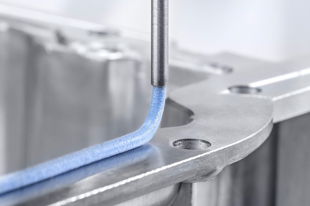
The article is not primarily about cell electrochemistry; it is about pack-level containment engineering under increasingly stringent thermal runaway safety regulations. The key technical subject is a formed-in-place gasket (FIPG) based on liquid silicone rubber (LSR) for EV battery housings, designed to maintain integrity under high-pressure, corrosive gas ejection, thermal shock, and sustained exposure to automotive underhood/enclosure environments.
From an engineering standpoint, this addresses a system-level failure mode: when a cell vents or enters thermal runaway, the enclosure seal becomes a critical barrier between the battery’s internal failure and the vehicle environment. The seal must preserve mechanical closure, pressure retention, moisture exclusion, and chemical resistance while being manufacturable at high volume with repeatable process control.
1) Assumed Cell Chemistry and Intrinsic Limitations
The article does not specify the cell chemistry. However, because it is framed around thermal runaway containment, gas pressure, and safety standard compliance, the most likely pack architectures include NMC/NCA high-energy lithium-ion cells or, less likely, LFP in a high-volume passenger EV context. The distinction matters because the thermal runaway severity, vent gas composition, and external sealing demand differ materially by chemistry.
Most Likely Assumption: NMC / High-Energy Lithium-Ion
For an EV battery requiring aggressive containment of corrosive gases and pressure, the underlying chemistry is likely NMC (nickel manganese cobalt) or a similar layered oxide system.
Why NMC is a plausible assumption
- Higher gravimetric and volumetric energy density than LFP.
- Greater adoption in long-range EV platforms.
- More severe runaway propagation risk than LFP.
- Stronger demand for robust enclosure sealing and vent management.
Intrinsic limitations of NMC
- Lower thermal stability: Layered oxide cathodes can release oxygen at elevated temperature, accelerating exothermic reactions.
- Higher runaway severity: Once decomposition initiates, self-heating can escalate rapidly.
- Electrolyte flammability: Carbonate electrolytes contribute to gas generation and fire propagation.
- Sensitivity to lithium plating during fast charge: Especially at low temperature or high SOC, which can trigger internal shorts and downstream thermal runaway events.
Alternate Possibility: LFP
If the platform is cost-focused or safety-regulated for fleet/commercial use, the chemistry could be LFP (LiFePO4). In that case, the article’s emphasis on sealing still makes sense, but the required thermal containment is usually less extreme than for NMC.
Intrinsic limitations of LFP
- Lower energy density: Requires larger pack volume for equivalent range.
- Still vulnerable to abuse and venting: LFP is more thermally stable, but the electrolyte remains flammable and overcharge can still produce gas.
- Fast-charge limitations remain: Especially at low temperature, lithium plating can occur on the graphite anode irrespective of cathode chemistry.
- Thermal management becomes geometry-driven: Because more cells are needed to achieve range, pack-level heat rejection and gradients become more difficult.
Solid-State: Less Likely, But Notable
Solid-state systems are not a strong fit for this article because the focus is on a conventional sealed housing, FIPG behavior, and high-volume automotive processing of a liquid elastomer. Solid-state cells reduce some electrolyte flammability concerns, but they introduce their own interface and pressure-control limitations.
Intrinsic limitations of solid-state
- Interfacial impedance: Solid-solid contact can degrade under cycling and thermal expansion mismatch.
- Stack pressure requirements: Many designs need persistent compressive preload, making housing sealing and mechanical compliance even more critical.
- Lower manufacturing maturity: Less aligned with current automotive FIPG pack sealing programs.
- Thermal hotspots still possible: Especially under high-rate charge/discharge due to localized interfacial resistance.
2) Seal Function in the Context of Battery Safety
The seal described is not a generic weather seal. It is a primary safety interface.
Functional requirements under thermal runaway
A battery enclosure seal must withstand:
- Pressure pulses from venting cells
- Corrosive vent gas exposure
- Hot particulate ejection
- Rapid transient temperature rise
- Long-term moisture ingress
- Dimensional mismatch between housing parts
The article’s emphasis on double-sided chemical adhesion and >2 MPa adhesive strength indicates the seal is intended to resist peel, shear, and blowout during an internal overpressure event. This is important because a seal that depends only on compression can lose contact locally when:
- flange flatness is imperfect,
- pressure becomes nonuniform,
- thermal cycling relaxes clamp load,
- or housing distortion occurs under load.
Why chemical bonding matters
A chemically bonded FIPG can provide:
- Better retention under dynamic pressure loading
- Improved resistance to seal creep and extrusion
- More stable contact during housing deformation
- Greater sealing reliability on complex 3D geometries
From a failure analysis perspective, the gas-load scenario is especially severe because vent gases can be both:
- hot enough to soften or embrittle certain polymers, and
- chemically aggressive enough to degrade interfacial adhesion.
Silicone elastomers are attractive here because they generally tolerate:
- wide temperature excursions,
- low compression set,
- and good chemical inertness relative to many organic gasket systems.
3) Thermal Management Challenges at Pack Level
Although the article is about a seal, its relevance is tightly coupled to the broader thermal design of the pack. A pack may remain safe only if it can:
- Reject cell-generated heat during normal operation,
- Limit thermal gradients under fast charge/discharge,
- Prevent propagation when a fault cell enters abuse.
Liquid Cooling Plate Design Constraints
Most automotive packs rely on liquid cooling plates under or around prismatic/pouch cells, or between modules. The seal/housing design must coexist with this thermal architecture.
Key engineering tradeoffs
- Contact area vs. flow resistance: More serpentine coolant paths improve heat transfer uniformity but increase pressure drop.
- Plate flatness and stack-up: Thermal interfaces depend heavily on contact quality; housing distortion can create local hot spots.
- Coolant channel placement: Channels must align with cell heat flux distribution, not just housing geometry.
- Mechanical decoupling: The seal must tolerate differential expansion between aluminum housings, steel reinforcements, polymers, and battery internals.
Thermal bottlenecks
- The largest thermal resistance is often not the coolant itself, but:
- cell-to-TIM interface,
- TIM-to-cold plate interface,
- cold plate spreading resistance,
- and enclosure-level thermal gradients.
An enclosure seal material with low thermal conductivity is acceptable at the perimeter, but if used in gap-fill or potting roles, it can inadvertently create thermal bottlenecks. That is why the article’s mention of separate thermal-management silicones is technically relevant: sealants and thermal interface materials must be engineered independently.
Thermal Gradients and Nonuniform Cell Aging
Uneven temperature fields cause:
- variable internal resistance,
- nonuniform SEI growth,
- accelerated aging at hot spots,
- and inconsistent charge acceptance.
Even a few degrees of gradient across a module can produce measurable imbalance over time, particularly in dense packs with limited coolant access.
Why this matters to sealing
If an enclosure seal locally insulates or changes housing stiffness, it can indirectly influence:
- platen compression,
- coolant plate alignment,
- and module thermal contact pressure.
So while the seal is not a cooling component, it participates in pack-level thermo-mechanical coupling.
Tab Cooling vs. Surface Cooling
This is highly relevant when considering cell format.
Prismatic/pouch cells
- Heat generation occurs throughout the jelly roll or stacked electrodes.
- Surface cooling is common because the largest area is available for conduction to a cold plate.
- Tab regions can become thermal and electrical hotspots due to current crowding and local resistance.
Tab cooling challenges
- Tabs can carry very high current density.
- Local Joule heating can exceed the average cell heat generation.
- Poor heat extraction at the tab can create localized thermal runaway initiation points.
- Mechanical sealing must not interfere with busbar thermal paths or tab-to-busbar construction.
Surface cooling limits
- Surface cooling is effective when the cell-to-plate thermal path is short and uniform.
- However, if one region is poorly clamped or separated by enclosure tolerances, thermal nonuniformity increases.
- Multi-layer sealing or structural adhesives can distort the flatness required for optimal contact.
In practice, pack design often balances:
- tab conduction path,
- cell face cooling,
- busbar heat spread,
- and enclosure stiffness.
4) Fast-Charging Constraints
The article does not explicitly discuss charging, but the safety standard context implies a battery must remain safe under high power stress, which includes fast charging. This is one of the most important electrochemical constraints linked indirectly to containment design.
Ionic Conductivity Limitations
At high C-rates, the battery must sustain:
- rapid lithium-ion transport through electrolyte,
- diffusion within porous electrodes,
- charge transfer at interfaces,
- and electronic conduction through current collectors and tabs.
Main fast-charge bottlenecks
- Electrolyte ionic conductivity: Limited by temperature and composition.
- Porous electrode tortuosity: Restricts ion transport deep into the electrode thickness.
- Solid-state diffusion in active material: Particularly limiting at high rates and low temperature.
- Charge-transfer kinetics: Overpotential rises sharply at high current density.
If transport cannot keep up with current demand:
- anode potential can drop to lithium plating territory,
- local temperature rises can accelerate side reactions,
- and cells may vent earlier due to gas generation.
Lithium Plating Risk at High C-Rates
Lithium plating is the dominant fast-charge hazard in graphite-based lithium-ion cells.
Conditions that promote plating
- Low cell temperature
- High SOC
- High charge current
- Elevated internal resistance
- Poor thermal uniformity across the pack
Why plating is dangerous
- Metallic lithium can form dendritic or mossy deposits.
- Plated lithium reduces cyclable lithium inventory, causing capacity fade.
- Dendrites can penetrate separators and create internal shorts.
- Side reactions consume electrolyte and produce gas, increasing vent risk.
- In severe cases, plating becomes a precursor to thermal runaway.
Relationship Between Fast Charge and Sealing
The connection is indirect but important:
- Fast charge increases heat generation and internal pressure risk.
- If thermal gradients are high, some cells reach plating thresholds earlier than others.
- A seal must survive not only catastrophic runaway, but also repeated subcritical gas events and pressure cycling that occur over pack life.
Thus, a robust enclosure seal is part of the safety chain, but it does not solve the electrochemical limit. It only contains one consequence of exceeding those limits.
5) Material Analysis of the LSR FIPG
Why a filler-free LSR is technically significant
A filler-free formulation can provide:
- more stable rheology,
- improved pumpability and dose repeatability,
- less abrasive wear on metering systems,
- and reduced variability in cure behavior.
For automated battery manufacturing, these characteristics are major advantages because waterproofing/sealing performance must remain consistent across long housings and complex geometries.
Adhesion and cure behavior
The combination of:
- pot life > 24 hours at room temperature
- rapid IR-assisted cure at 140 °C
suggests a process window designed for: - high-volume line throughput,
- rework tolerance,
- and integration into flexible assembly sequences.
Failure modes addressed
The material is likely intended to resist:
- blowout under transient pressure
- moisture ingress
- seal relaxation after thermal cycling
- interfacial degradation from vent gases
- chemical attack from electrolyte decomposition products
6) Practical Engineering Implications for Battery Pack Designers
What this means for pack architecture
Battery designers should interpret this type of seal innovation as a response to three converging trends:
- Higher energy density cells,
- More stringent thermal runaway containment requirements,
- Greater automation in battery enclosure assembly.
Design considerations
- Verify flange stiffness and flatness under thermal and mechanical load.
- Model pressure transients from single-cell vent events.
- Validate adhesion under exposure to electrolyte decomposition gases.
- Consider seal interaction with enclosure venting pathways.
- Ensure thermal interfaces are not compromised by perimeter sealing strategy.
Validation tests that matter
- Pressure burst and pressure hold after thermal shock
- Hot gas corrosion exposure
- Thermal cycling with clamp-load relaxation
- Moisture ingress testing
- Adhesion retention after coolant and electrolyte exposure
- Multi-axis vibration plus thermal aging
7) Bottom-Line Technical Assessment
This article is fundamentally about battery enclosure failure containment, not cell innovation. The enabling technology is a chemically bonded silicone FIPG seal that improves pack integrity under overpressure and thermal abuse.
Technical takeaway
- If the pack uses NMC, the seal is especially relevant because the chemistry has higher runaway severity and greater gas/heat release risk.
- If the pack uses LFP, the seal still matters, but the primary benefit shifts more toward manufacturing robustness, moisture sealing, and secondary containment.
- For either chemistry, fast charging remains constrained by ionic transport and lithium plating risk, which can still produce the very abuse scenarios the seal is designed to contain.
- The broader thermal system—especially liquid cooling plates, thermal gradients, and tab-region hot spots—remains the primary determinant of whether the enclosure ever needs to perform its ultimate containment function.
If you want, I can also turn this into a battery teardown-style failure analysis memo with sections on likely pack stack-up, seal cross-section, process flow, and validation test matrix.