Technical Interpretation of the Article
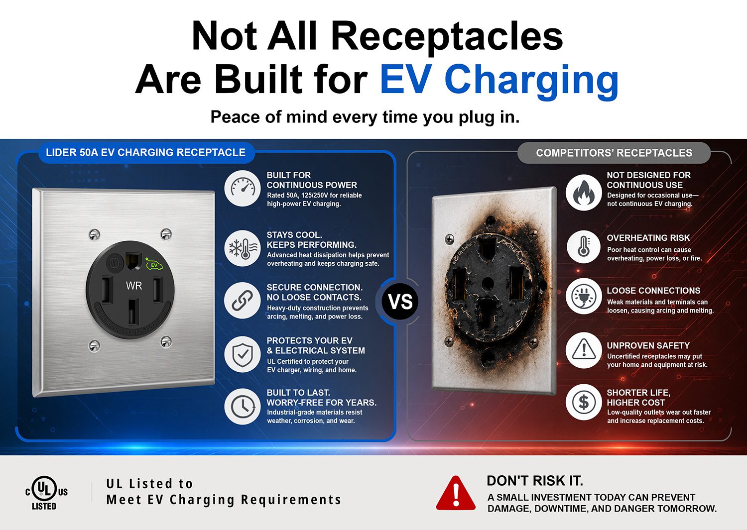
The article itself is not about battery chemistry or pack internals; it concerns the AC charging interface used in Level 2 EV charging: a NEMA 14-50 receptacle certified with UL Electric Vehicle Marking. From an engineering standpoint, this is a distribution-side reliability component, but it materially affects the battery system because poor AC-side terminations can create voltage drop, resistive heating, intermittent discontinuities, and thermal derating events that indirectly influence onboard charger behavior and, ultimately, battery charging consistency.
The key technical signal in the article is that these receptacles are being positioned for sustained EV charging duty, which implies a recognition that EV charging is not equivalent to intermittent appliance loading. The relevant engineering question is therefore not the receptacle alone, but how this interface supports stable power transfer into the vehicle’s onboard charger, battery thermal management system, and cell-level electrochemistry.
1) Assumed Cell Chemistry and Intrinsic Limitations
Because the article does not specify a vehicle platform, the chemistry must be inferred based on current EV charging use cases. For most mass-market AC-charging EVs in North America, the dominant chemistries are:
Likely chemistry: NMC/NCA for mainstream long-range EVs
If the EV is a typical passenger vehicle with moderate-to-high energy density, the likely chemistry is:
- NMC (nickel manganese cobalt oxide), often in 622/721/811 variants
- or NCA (nickel cobalt aluminum oxide)
Intrinsic limitations of NMC/NCA
These chemistries offer high gravimetric and volumetric energy density, but they are constrained by:
- Thermal runaway sensitivity: cathode oxygen release at elevated temperature and high state-of-charge
- Calendar aging accelerated by high SOC storage
- Plating susceptibility during low-temperature/high-current charging
- Cathode microcracking due to H2-H3 phase transitions in high-nickel forms
- SEI growth on graphite anodes, which drives impedance increase over time
For AC Level 2 charging, the current is typically moderate relative to DC fast charge, so the battery is not usually the bottleneck. However, prolonged high-SOC top-off charging still imposes lithiation imbalance and impedance growth stress, particularly in high-nickel cells where upper-voltage operation is less forgiving.
Possible alternative chemistry: LFP in cost-focused EVs
If the vehicle is a cost-optimized EV or fleet vehicle, the chemistry could be:
- LFP (lithium iron phosphate)
Intrinsic limitations of LFP
LFP is thermally robust but has lower energy density and different charging behavior:
- Lower volumetric and gravimetric energy density, increasing pack size for equivalent range
- Flatter OCV-SOC curve, complicating SOC estimation
- Lower low-temperature charge acceptance
- Higher polarization under cold charging
- Less aggressive thermal runaway behavior, but not immunity to abuse
For AC charging, LFP can tolerate good cycle life, but it is especially sensitive to cold-charge restrictions because lithium plating can still occur if the anode potential falls too low during high current charge at low temperature.
Solid-state chemistry: not implied by the article
The article does not suggest solid-state cells. A solid-state battery would fundamentally change charging and thermal management assumptions:
- Potentially improved safety margins
- Different interfacial resistance behavior
- Different fast-charge bottlenecks at the solid-solid interface
- Still unresolved manufacturability and stack pressure issues
Given the context of a standard AC charging receptacle product, solid-state is not a reasonable assumption for the underlying application.
2) Thermal Management Challenges in the Charging Chain
Although the receptacle is external infrastructure, the article explicitly emphasizes sustained electrical load and high-temperature-resistant contacts, which is a strong indicator that thermal management at the connector interface is a critical reliability issue. The same thermal principles govern battery pack charging, particularly when the charger operates for hours at a steady current.
AC charging thermal path: from receptacle to battery
The thermal chain includes:
- Receptacle contact interface
- Plug blades
- EVSE cordset
- Onboard charger rectification stage
- Battery pack current distribution
- Cell entropic and resistive heat generation
Each stage contributes losses. Even modest contact resistance at the receptacle can produce local hotspots:
[
P = I^2R
]
At 40–50 A continuous loading, a small increase in contact resistance materially elevates temperature. This is particularly important for NEMA 14-50 applications because real-world terminal looseness, oxidation, spring-force relaxation, and insertion wear can drive elevated interface resistance over time.
Receptacle thermal reliability implications
The article’s emphasis on “secure connection performance under sustained electrical load” points to a known failure mode: contact heating-induced degradation. In charging applications, repeated thermal cycling can cause:
- Spring force loss in copper alloy contacts
- Oxide film growth
- Differential thermal expansion at conductor terminations
- Torque relaxation at screws/lugs
- Progressive increase in micro-ohmic resistance
That can create a positive feedback loop:
- higher resistance → more heating → more oxidation/annealing → even higher resistance
Battery pack thermal management: liquid cooling plate design
Once power reaches the pack, the cell chemistry determines the plausible thermal load profile.
For NMC/NCA packs, a liquid-cooled cold plate is typically necessary for consistent charging performance, especially at higher C-rates or elevated ambient temperatures. Important design variables include:
Plate architecture
- Serpentine coolant channels: good residence time, higher pressure drop
- Parallel microchannels: improved heat transfer, but high clogging sensitivity and manifold balancing challenges
- Brazed aluminum cold plates: high thermal conductivity and manufacturability
- Embedded dielectric cooling: less common, more complex, but can improve localized extraction
Thermal resistance stack
The limiting chain is often not coolant heat capacity, but:
- cell can-to-TIM resistance
- TIM pump-out or dry-out
- plate-to-cell flatness and interface pressure
- manifold maldistribution
- local hotspots near tabs/junctions
Thermal gradients within the cell array
Even if average pack temperature is acceptable, temperature gradients drive performance mismatch across series cells. Consequences include:
- Non-uniform aging rate
- SOC divergence
- Balancing losses
- Different internal resistance among cells
- Uneven lithium plating risk during charge
A few degrees Celsius of gradient can materially alter charge acceptance. In tightly packed modules, edge cells often cool better than interior cells unless the cooling architecture is carefully balanced.
Tab cooling vs. surface cooling
This is one of the most underappreciated design issues in EV battery engineering.
Surface cooling
- Heat is extracted primarily through the cell can surface or module baseplate
- Advantage: simpler architecture, large area contact
- Limitation: thermal bottlenecks remain at tab-to-electrode junctions
- Risk: center of jelly roll/pouch or tab region can remain hotter than the measured surface temperature
Tab cooling
- Thermal extraction is applied closer to the current collection point
- Advantage: directly mitigates ohmic heating at high current entry/exit points
- Particularly valuable during fast charge because Joule heating density is highest near tabs and current collectors
- Limitation: more complex mechanical design, sealing, and electrical isolation requirements
For pouch cells in particular, tab heating can be severe because current density is concentrated in localized foil connections. For cylindrical cells, the equivalent concern is axial heat extraction from the tab/terminal region. If the pack only measures surface temperature, the true hot spot may be underreported.
Why this matters even in AC charging
The article is about AC charging receptacles, but the battery relevance is that the charging profile is usually long-duration and can still induce:
- persistent resistive heating
- cumulative thermal soak
- SOC-dependent tapering behavior near the top of charge
Even at Level 2, a poorly cooled pack can enter thermal limiting conditions, especially when ambient temperature is high or the battery is already warm from driving.
3) Fast-Charging Constraints: Ion Transport and Lithium Plating
Although the article does not mention DC fast charging, any analysis of EV charging hardware should acknowledge the higher-level electrochemical limits that ultimately constrain charge acceptance.
Ionic conductivity and transport limitations
Charging rate is limited by how rapidly lithium ions can migrate through:
- electrolyte
- separator pores
- solid-phase diffusion in active materials
- charge-transfer interfaces at anode and cathode
At elevated C-rates, the cell behaves increasingly as a transport-limited system rather than an energy-storage system. Problems include:
- electrolyte concentration polarization
- anode overpotential rise
- cathode depletion near particle surfaces
- diffusion gradients inside active particles
The result is that the anode potential can approach 0 V vs. Li/Li+, which is the threshold region where metallic lithium deposition becomes possible.
Lithium plating risk
Lithium plating is a critical degradation mechanism during high-rate charging, especially under:
- low temperature
- high SOC
- high C-rate
- aged cells with elevated impedance
- uneven thermal profiles
Mechanism
If lithium insertion into graphite cannot proceed fast enough, lithium ions are reduced as metallic lithium on the anode surface instead of intercalating into graphite. This leads to:
- irreversible capacity loss
- dead lithium formation
- dendritic growth risk
- SEI destabilization
- potential internal short-circuit hazard
Why low temperature is especially dangerous
At low temperature:
- electrolyte viscosity increases
- ionic conductivity decreases
- diffusion coefficients fall
- anode charge-transfer kinetics slow down
This raises overpotential and makes plating much more likely. For this reason, modern EVs aggressively manage preconditioning before fast charge.
Relevance to charging hardware
A high-quality receptacle like the one described in the article does not increase cell charge acceptance directly, but it reduces charge-side losses that could otherwise worsen system thermal burden. Stable AC input means:
- reduced nuisance heating at the inlet
- more predictable onboard charger efficiency
- less input voltage sag
- fewer thermal interruptions
That said, the battery still sees the same fundamental electrochemical constraints. Hardware improvements at the outlet do not eliminate:
- diffusion limits
- SEI growth
- plating sensitivity
- cell-to-cell thermal mismatch
Engineering Assessment of the Product Context
The article is essentially about improving the mains-side reliability envelope for EV charging. From a battery engineering perspective, that matters because EV charging reliability is a system-level property spanning:
- AC infrastructure
- connector metallurgy
- thermal rise at terminations
- onboard conversion
- pack thermal management
- cell electrochemistry
The UL Electric Vehicle Marking implies that the receptacle has been evaluated for higher duty-cycle, sustained-load use, which is essential because legacy household-grade interfaces often fail under prolonged EV charging conditions due to:
- contact resistance instability
- heat accumulation
- reduced spring contact retention
- insulation aging
For EV programs using NMC/NCA packs, sustained charging quality is especially important because high-energy-density chemistries are less tolerant of thermal abuse and overvoltage stress. For LFP, the concern shifts toward cold-charge behavior and charge control accuracy. In both cases, infrastructure reliability is a prerequisite for safely preserving battery life.
Bottom Line
From a teardown-engineering perspective, the article is not about the battery itself, but it highlights a critical charging-chain reliability component that directly affects battery life and safety.
Core technical takeaways
- Most likely chemistry: NMC/NCA or LFP, depending on EV segment; solid-state is not implied.
- Intrinsic limitations:
- NMC/NCA: thermal sensitivity, plating risk, aging at high SOC
- LFP: lower energy density, cold-charge limitations, SoC estimation challenges
- Thermal management challenge: sustained load demands low-resistance contact interfaces and, at the pack level, carefully engineered liquid cooling with attention to gradients and tab hotspots.
- Fast-charge constraint: charge acceptance is fundamentally governed by ionic transport and anode kinetics; lithium plating remains the key failure mode at high C-rate, low temperature, and high SOC.
If you want, I can also convert this into a battery teardown-style failure analysis memo with sections like “likely design intent,” “probable failure modes,” and “engineering validation tests.”