Core Technology Extracted
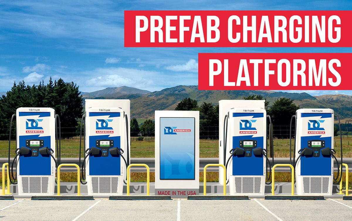
The article is not fundamentally about battery technology; it is about prefabricated, skid-mounted EV charging infrastructure. From an engineering perspective, the relevant technology stack includes:
- Modular DC fast-charging power architecture
- Prewired switchgear / panelboard / transformer integration
- Top-accessible raceway routing
- Site-level commissioning prior to deployment
- Distributed power management / oversubscribed charging topology
- Optional integration of battery energy storage systems (BESS)
For EV battery engineers, the significance is indirect but important: these systems determine the charge envelope, ramp rate, session duration, and thermal-electrochemical stress profile experienced by the traction battery. In other words, charging infrastructure topology strongly influences battery degradation mechanisms.
Assumed Cell Chemistry and Intrinsic Limitations
Likely Chemistry Context: LFP vs NMC in Commercial DC Fast Charging
The article does not state a battery chemistry, but the use case implied by fleet charging, public DC fast charging, and oversubscribed high-power stations suggests the dominant chemistries are:
- NMC/NCA in high-energy passenger vehicles and some light-duty commercial platforms
- LFP increasingly common in cost-sensitive fleets, urban duty cycles, and some commercial EVs
From a charger engineering standpoint, the infrastructure is chemistry-agnostic, but the battery response to fast charging is not.
LFP Intrinsic Limitations
If the vehicle employs LFP, the limiting factors are less about cathode thermal instability and more about:
- Lower electronic/ionic transport kinetics at low temperature
- Flatter OCV-SOC curve, making SOC estimation more difficult during high-power charging
- Reduced specific energy, which pushes higher pack mass for a given range
- Limited fast-charge acceptance at cold temperatures, due to anode diffusion and plating risk
LFP’s tolerance for thermal abuse is better than layered oxides, but its charge acceptance window can be narrow at low temperature, especially when the pack is not actively preconditioned.
NMC Intrinsic Limitations
For NMC, the dominant issues are:
- Higher specific energy, but greater thermal and electrochemical sensitivity
- More pronounced cathode degradation at elevated voltage
- Accelerated impedance growth under repeated high-C charging
- Higher sensitivity to lithium plating when the anode overpotential becomes excessive
NMC packs are more likely to prioritize energy density over charge durability, which makes them especially dependent on BMS charge derating, thermal preconditioning, and careful charger/current coordination.
Solid-State: Not Implied
Nothing in the article supports a true solid-state assumption. If anything, the mention of conventional DCFC hardware, existing charger manufacturers, and standard commissioning indicates a mainstream liquid-electrolyte pack ecosystem. Solid-state would impose different charger control constraints and is not indicated here.
Battery-Level Limitations Relevant to This Charging Model
The infrastructure described supports high-power, rapidly deployable DC charging, which tends to expose the following intrinsic battery limits:
- Ohmic heating in tabs, busbars, jellyroll, and current collectors
- Mass-transport limitation in the graphite anode
- Electrolyte transport resistance
- Lithium plating risk at high SOC, low temperature, or high current
- Cell-to-cell imbalance amplification under rapid charge termination
- Pack thermal non-uniformity due to external cooling asymmetries
For fleet and public DC charging, the practical battery challenge is not only peak power, but whether that power can be sustained without driving the anode potential below 0 V vs Li/Li+.
Theoretical Thermal Management Challenges
What the Infrastructure Implies for Thermal Load Profiles
A prefabricated skid-mounted DCFC site can enable very high utilization and dynamic power allocation. From the battery perspective, this means:
- More frequent high-C charging sessions
- Less idle time for pack cool-down
- Increased probability of back-to-back charging at elevated pack temperatures
- More demand for vehicle-side thermal preconditioning
The charger itself does not manage battery heat directly, but by shortening installation friction and increasing throughput, it can increase the thermal duty cycle imposed on vehicles.
Liquid Cooling Plate Design Constraints
For liquid-cooled traction packs, the bottleneck is generally not coolant flow availability but heat extraction uniformity.
Key design constraints:
- Coolant channel placement relative to heat-generating cell regions
- Pressure drop vs. heat transfer tradeoff
- Contact resistance between cell can/module and cooling plate
- Manifold distribution uniformity
- Flow maldistribution across parallel channels
- Thermal runaway propagation mitigation
Theoretical issue with fast charging:
High charging current causes heat generation proportional to:
- I²R losses in tab, collector, interconnect, and electrolyte resistance
- Entropic heat contribution, which varies with SOC and chemistry
- Localized hotspots near tabs and current collector transitions
If the cooling plate is only effective at the module base, the cell core may experience significant gradients. This is especially problematic for prismatic and pouch cells, where in-plane thermal conduction and through-thickness gradients differ strongly.
Thermal Gradient Risk
Fast charging amplifies radial and axial gradients within the cell:
- Tab-adjacent regions can be significantly warmer than mid-span regions
- Surface-cooled pack architectures can undercool the cell core
- Edge cells may run cooler than interior cells due to boundary exposure
- Pack-level gradients produce uneven electrochemical aging
Why gradients matter:
Even a modest temperature differential can cause:
- Local current density non-uniformity
- Accelerated SEI growth in hotter regions
- Earlier lithium plating onset in colder regions
- SOC estimation errors across the pack
In practical terms, the charger can deliver 350 kW, but if the pack’s internal temperature field is non-uniform, the BMS will derate current long before the charger reaches its theoretical limit.
Tab Cooling vs Surface Cooling
Tab cooling
Tab cooling is attractive because it targets the electrical/thermal hotspot closest to the primary resistive losses. However:
- It is mechanically complex
- It can suffer from limited thermal contact area
- It must coexist with high-current interconnect design
- It may not adequately cool the cell core
Surface cooling
Surface cooling, especially via a cold plate, is easier to integrate at pack level but often has:
- Lower local heat flux removal exactly where the tab hotspot is
- Larger thermal lag
- Higher gradients in thick-format cells
- Sensitivity to interface material performance
Engineering implication
For high-C DC fast charging, the optimal architecture is often hybrid:
- Surface cooling for bulk heat removal
- Enhanced tab/collector thermal management for hotspot suppression
- Control logic that limits current based on coldest-cell and hottest-cell boundaries, not just average pack temperature
Fast-Charging Constraints
Ionic Conductivity and Charge Transport Limitations
Fast charging is ultimately limited by the coupled transport of:
- Lithium ions through the electrolyte
- Lithium through the solid active material
- Electrons through current collectors and interconnects
- Heat through the thermal stack
At high C-rates, the concentration gradient in the electrolyte becomes steep, increasing polarization. This leads to:
- Higher cell overpotential
- More voltage rise under charge
- Earlier charge termination
- Reduced usable charge acceptance
Practical outcome
A charger may be rated for very high output, but battery acceptance is bounded by:
- electrode thickness
- porosity/tortuosity
- ionic conductivity
- SEI resistance
- temperature
Thicker electrodes, while favorable for cost and energy density, worsen diffusion path length and reduce fast-charge performance.
Lithium Plating Risk at High C-Rates
Lithium plating occurs when the graphite anode cannot intercalate lithium ions as fast as they arrive. Conditions that increase plating risk include:
- Low temperature
- High SOC
- High charge current
- Poor thermal uniformity
- Aging-induced impedance growth
- Cell imbalance
Why this matters in the article’s deployment model
The article emphasizes rapid deployment and throughput. That implies charging infrastructure likely supports:
- frequent short dwell times
- opportunistic high-power sessions
- fleet depots with narrow operational windows
These are exactly the conditions where plating risk becomes a design limiter, because operators are incentivized to maximize kW delivered per minute.
BMS and Charger Coordination
The infrastructure described includes precommissioning and onboard/on-site control. From a battery engineering viewpoint, this is beneficial only if the charger obeys strict battery-side constraints:
- SOC-dependent current taper
- temperature-dependent derating
- voltage limit enforcement
- cell balancing awareness
- communication latency robustness
Without tight charger-BMS coordination, the site may offer more power than the pack can safely accept, creating:
- accelerated degradation
- capacity loss
- impedance rise
- warranty exposure
Engineering Interpretation of the Prefabricated Charging Approach
Why It Matters to Battery Pack Design
A skid-mounted, precommissioned charging platform reduces installation time, but for battery systems it also enables:
- Faster site deployment of DCFC capable of high throughput
- Easier scaling from one charger topology to another
- Distributed architectures that support dynamic power allocation
- Potential pairing with BESS to lower grid stress and offer smoother DC bus operation
This is important because battery pack design increasingly has to be optimized against real-world charging topology, not just nominal charger rating.
System-Level Coupling to Battery Degradation
The key battery-relevant effect is utilization intensity:
- more sessions per day
- higher average charge power
- less time for thermal recovery
- more dependence on vehicle preconditioning
Thus, the infrastructure indirectly increases the importance of:
- robust thermal design margin
- low-impedance cell architecture
- precise BMS algorithm calibration
- validated fast-charge charge acceptance maps
Conclusion
The article describes a prefabricated EV charging infrastructure platform, but the battery engineering implications are significant. The assumed vehicle batteries are most likely LFP in cost-sensitive fleets and NMC in higher-energy applications, with no evidence for solid-state.
From an engineering standpoint, the main constraints are:
- Thermal: maintaining low gradients, suppressing tab hotspots, and ensuring liquid cooling plate effectiveness under repeated high-power sessions
- Electrochemical: preserving ionic transport margin to avoid polarization collapse and lithium plating
- Operational: ensuring charger power availability does not exceed battery acceptance capability
In short, the value of the charging platform is not only installation speed. It is the ability to support a charging ecosystem that is more scalable, more modular, and more demanding on the battery’s thermal-electrochemical design envelope.