Technical Interpretation of the Cell Architecture
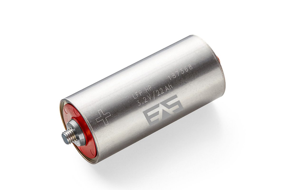
The article describes a large-format cylindrical LFP cell (22 Ah, UHP-601300-LFP-22) paired with an acetonitrile-based electrolyte (Asahi Kasei Acetolyte). The key engineering implication is that the cell chemistry remains LFP, but the electrolyte system is being used as the major enabler for higher power capability.
From a teardown/validation perspective, this is not a chemistry transition to a fundamentally different cathode or anode platform; it is a high-power LFP optimization that likely targets:
- reduced ohmic polarization,
- improved low-temperature power retention,
- reduced voltage sag under severe pulse loads,
- and better discharge/charge acceptance at high C-rate.
This is especially relevant because LFP cells are often constrained not by the cathode crystal stability itself, but by electrolyte transport, separator resistance, electrode tortuosity, and heat removal at high current density.
1. Assumed Cell Chemistry and Intrinsic Limitations
LFP as the most plausible base chemistry
The article explicitly identifies the cell as LFP (lithium iron phosphate). That implies:
- Cathode: LiFePO₄
- Anode: almost certainly graphite, or graphite-dominant with possible silicon-free formulation for cycle robustness
- Electrolyte: acetonitrile-based low-resistance formulation
- Format: large-format cylindrical, which usually places higher demands on internal heat extraction than prismatic or pouch cells due to the radial heat path and current collection geometry
Why LFP is suitable for high-power use
LFP is inherently attractive for high-power EV and industrial applications because it offers:
- strong thermal stability,
- low oxygen release risk at abuse conditions,
- high cycle life,
- lower material cost,
- and relatively flat voltage plateau.
Its olivine structure has good structural stability during lithiation/delithiation. In practice, this makes LFP more tolerant of high cycling throughput than nickel-rich layered oxides.
Intrinsic limitations of LFP
Despite the safety and life advantages, LFP has several inherent penalties:
Low intrinsic electronic conductivity
LFP is electronically insulating compared with NMC. Commercial cells therefore rely heavily on:
- carbon coating of particles,
- conductive additives,
- optimized electrode porosity,
- and low-thickness current paths.
If the electrolyte resistance is reduced, the limiting factor can rapidly shift to solid-state electron transport in the composite electrode and charge-transfer kinetics at the interface.
Lower volumetric energy density
Compared with NMC-class materials, LFP has lower energy density at the pack level because:
- the nominal voltage is lower,
- the cathode specific capacity is modest,
- and more inactive material is needed for comparable power handling and mechanical stability.
A high-power LFP cell can therefore be commercially attractive only when the application values cycle life and power more than maximum range per kilogram.
Polarization at high current density
At 25 C to 40 C discharge levels, polarization becomes the dominant behavior:
- ohmic polarization in electrolyte/separator,
- charge-transfer polarization at both electrodes,
- concentration polarization from salt depletion in porous electrodes,
- and localized current crowding near tabs or terminals.
The article’s reported jump from 1,550 W/kg to 2,550 W/kg suggests that the conventional electrolyte was a major bottleneck, not the LFP cathode alone.
What the acetonitrile electrolyte is actually solving
Acetonitrile-based electrolytes are typically pursued because they can provide:
- higher ionic conductivity than standard carbonate systems,
- lower viscosity,
- better low-temperature transport,
- and reduced polarization at high rates.
This improves power by lowering internal resistance. However, the benefit is not “free”; acetonitrile systems must still manage:
- narrower practical electrolyte stability windows depending on additive package,
- solvent volatility,
- seal compatibility,
- gas generation behavior,
- and long-term compatibility with graphite SEI formation.
In other words, the cell may gain power at the expense of manufacturing complexity and chemical containment requirements.
2. Theoretical Thermal Management Challenges
High-power cylindrical LFP generates a different thermal problem than high-energy cells
At 40 C continuous discharge, the fundamental issue is not just average heat generation, but spatial heat concentration. In a cylindrical cell, current density and thermal gradients are rarely uniform. Heat generation follows:
- ( I^2R ) losses in electrodes, current collectors, tabs, and electrolyte,
- entropic heat depending on SOC and temperature,
- and localized polarization heat in regions of poor ionic access.
As the article cites 880 A continuous discharge, the cell must manage extremely high internal current density. Even if the electrolyte’s ionic resistance is reduced, the remaining dissipation can still be substantial.
Liquid cooling plate design implications
For EV deployment, a cell like this would almost certainly require a pack architecture with aggressive thermal management, potentially including:
- direct or indirect liquid cooling,
- a high-conductivity cell-to-coolant heat path,
- and controlled contact pressure to reduce thermal contact resistance.
Key issue: cylindrical geometry limits heat extraction path
Unlike pouch cells, cylindrical cells reject heat primarily through:
- the outer can surface,
- terminal regions,
- and possibly the base cap depending on design.
The cell core is the hottest region during heavy discharge/charge because heat must conduct radially outward through wound jelly roll layers. This produces a radial thermal gradient:
- hottest at the center,
- progressively cooler near the can surface,
- with terminal hot spots depending on current collector geometry.
If the liquid cooling strategy only contacts the exterior can, the center-core temperature can still become the limiting factor.
Coolant plate thermal resistance
In real pack design, the total thermal path includes:
- cell-to-interface material,
- interface material-to-cooling plate,
- plate-to-coolant convection,
- and coolant-side thermal boundary layers.
Even with a high-performance electrolyte, the thermal bottleneck may move into the pack-level thermal interface. For sustained 5 C charge / 5 C discharge cycling, the system must maintain cell temperature in a narrow band, otherwise cycle life will degrade rapidly.
Thermal gradients and degradation modes
High thermal gradients inside the cell can trigger several failure or aging mechanisms:
Non-uniform lithium intercalation
Temperature variation changes local kinetics. The hotter region charges/discharges faster, leading to:
- current imbalance within the jelly roll,
- local SOC heterogeneity,
- and uneven aging of electrode regions.
Mechanical stress due to differential expansion
The separator, electrodes, and current collectors expand differently with temperature. Repeated gradients can accelerate:
- electrode delamination,
- contact loss,
- and microcrack formation in active material particles or binder networks.
Elevated local SEI growth
The cooler regions and high-overpotential zones often show thicker SEI growth. In high-power cycling, aging can become highly localized, reducing usable capacity before average cell metrics indicate failure.
Tab cooling vs. surface cooling
This article’s power levels suggest that tab and terminal thermal management is likely as important as external surface cooling.
Surface cooling
Surface cooling is effective for average cell temperature control, but at extreme C-rates it may not adequately address:
- internal core heating,
- terminal current crowding,
- and localized Joule heating near current collectors.
Tab cooling
Tab or terminal cooling is valuable because:
- current collectors can become major heat sources at very high current,
- terminal interfaces can develop large resistive losses,
- and localized heating can induce connector degradation.
For a cylindrical cell, the equivalent is often not a traditional pouch tab but rather end-cap and collector-path cooling considerations. If current is entering/exiting through the top cap structure, that region can become a thermal hotspot under 40 C discharge or 5 C charge.
Engineering tradeoff
A robust design may need a hybrid thermal solution:
- surface cooling for bulk heat removal,
- conductive end-cap heat spreading for terminal hotspots,
- and pack-level flow balancing to avoid unit-to-unit temperature spread.
Why acetonitrile improves thermal margins but does not eliminate them
A lower-resistance electrolyte reduces heat generation, which helps thermal management. However:
- reduced ohmic heating does not eliminate concentration polarization at high SOC,
- lower viscosity improves transport but can expose new charge-acceptance limits,
- and the cell still must reject the residual heat at a rate compatible with its thermal mass and cooling architecture.
So the electrolyte improves the thermal envelope, but pack design remains the governing constraint for sustained high-C operation.
3. Fast-Charging Constraints and Lithium Plating Risk
Why high-rate charging is more difficult than high-rate discharge
The article emphasizes 5 C charge acceptance and 60 C pulse discharge capability. These are not equivalent challenges.
Discharge at high rate mainly stresses:
- ohmic losses,
- thermal rejection,
- and voltage sag.
Charge at high rate adds a more dangerous constraint: anode lithiation kinetics. If the graphite anode cannot intercalate lithium fast enough, metallic lithium can plate on the anode surface.
Ionic conductivity as the first limiter
Acetonitrile-based electrolytes likely improve charge acceptance by increasing:
- bulk ionic conductivity,
- low-temperature mobility,
- and salt transport in the separator and porous electrodes.
This reduces electrolyte polarization, which is critical because at high C-rate the electrolyte often becomes a rate-limiting pathway. However, the electrolyte is only one part of the chain.
Remaining transport bottlenecks
Even with improved electrolyte conductivity, fast charging can still be limited by:
- solid-phase diffusion in graphite particles,
- interfacial charge-transfer resistance,
- separator tortuosity,
- electrode pore-filling constraints,
- and local current crowding.
In large-format cylindrical cells, long current paths exacerbate these effects. If the electrode coating is thick, the risk of lithium plating rises because the anode surface potential can approach 0 V vs. Li/Li+ before the total cell voltage indicates a problem.
Lithium plating mechanism at high C-rate
Lithium plating occurs when:
- the anode surface becomes saturated with incoming lithium ions faster than it can intercalate them,
- the electrode potential drops to near or below the Li/Li+ deposition threshold,
- or local temperature and SOC conditions cause nonuniform transport.
This is not simply a “high current” issue; it is a current density plus temperature plus SOC issue.
Conditions that increase plating risk
- low temperature charging,
- high SOC charging,
- thick graphite electrodes,
- inadequate electrolyte wetting,
- long diffusion pathways,
- and inhomogeneous compression or current distribution.
Why the acetonitrile electrolyte helps, but only partially
Because acetonitrile formulations are more conductive, they reduce the electrolyte’s contribution to overpotential. This lowers the probability of plating under otherwise similar conditions. But the real fast-charge ceiling will still be determined by:
- graphite anode kinetics,
- local heat removal,
- SEI impedance growth,
- cell-level current distribution,
- and battery management system controls.
For a cell declared capable of 5 C charge, the manufacturer likely assumes a tight thermal window and defined SOC/temperature constraints. In practical EV use, maximum charge rate is almost always derated at low temperature and high SOC to avoid plating.
Cycle life implications of high-rate operation
The reported 2,400 cycles at 5 C charge / 5 C discharge, 100% DOD, room temperature is notable. However, from an engineering standpoint, the real questions are:
- What is the cycle-life test temperature profile?
- What is the allowable SOC band?
- Was the test conducted with active liquid cooling?
- What is the impedance growth trajectory over life?
- How much lithium inventory loss is attributable to SEI growth versus plating?
At 5 C charge, even small inefficiencies translate into significant heat and degradation. Cycle-life retention at room temperature does not automatically translate to robust fast charging in cold ambient conditions, where plating risk escalates sharply.
4. System-Level Implications for EV Integration
Likely best-fit applications
This cell appears better suited for applications where:
- power density matters more than energy density,
- fast turnaround charging is critical,
- and thermal management infrastructure is strong.
That makes it a candidate for:
- low-voltage EV batteries,
- industrial vehicles,
- aerospace ground support,
- high-duty-cycle fleets,
- and possibly buffer/storage subsystems.
What pack engineers must validate
Before OEM adoption, engineers would need to validate:
- electrolyte stability over temperature cycling,
- venting behavior and gas generation,
- seal integrity with acetonitrile exposure,
- coolant interface efficiency,
- thermal uniformity across modules,
- charge derating logic,
- and abuse response under overcharge/high ambient scenarios.
Core engineering conclusion
This is best understood as a high-power LFP cell enabled by an advanced low-resistance electrolyte, not as a chemistry breakthrough in the cathode itself. The main engineering value is the shift in bottleneck: from electrolyte-limited rate capability toward thermal, anode-kinetic, and pack-level integration limits.
At the cell level, the acetonitrile electrolyte likely improves:
- ionic transport,
- power output,
- and low-temperature performance.
At the system level, however, the dominant challenges remain:
- radial thermal gradients in cylindrical geometry,
- terminal and current-collector hotspot management,
- fast-charge lithium plating avoidance,
- and maintaining uniform electrochemical utilization across the wound electrode stack.
If you want, I can also turn this into a teardown-style B2B technical memo with sections for materials, cell design, thermal architecture, failure modes, and OEM validation tests.