Technical Interpretation of the Core Technology
The article is fundamentally about magnetics for power conversion in EV charging and power electronics, not batteries per se. However, the implications are directly relevant to battery charging architecture, because the cited inductors are positioned in the DC-link, input filter, DC-DC conversion, and PFC stages that define charger efficiency, thermal load, and dynamic stress on the battery pack.
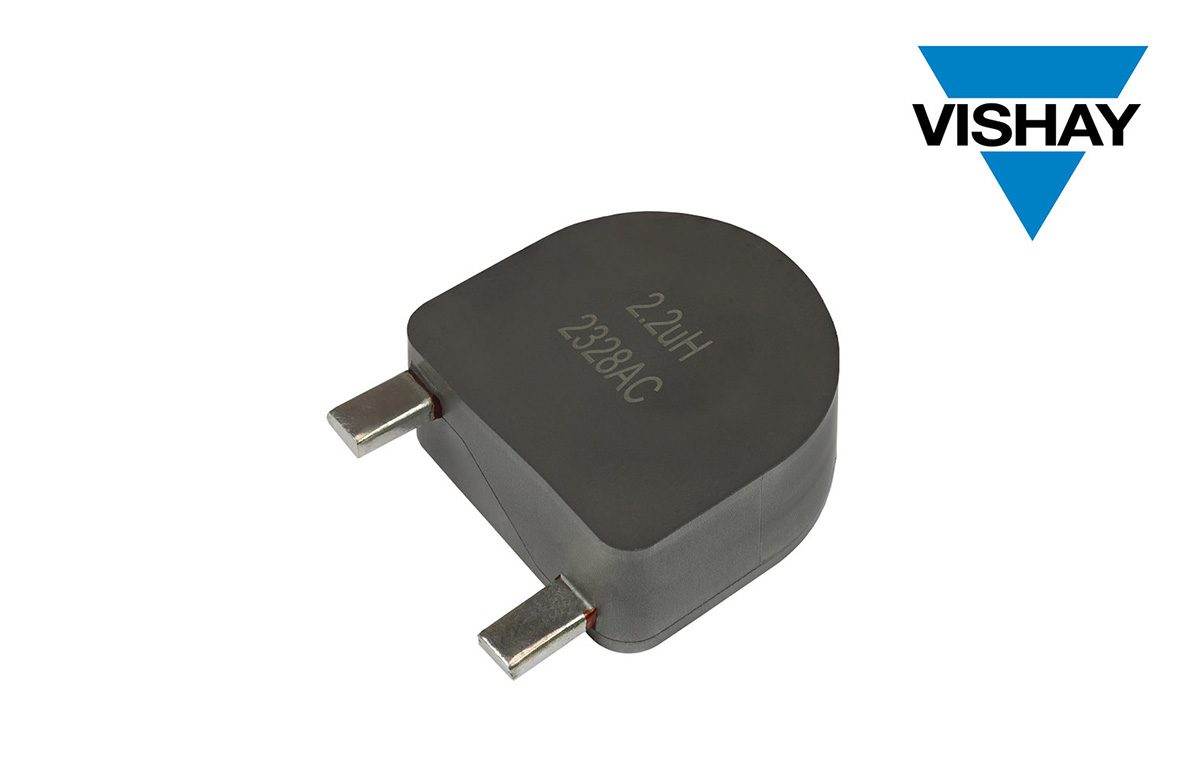
The core technology is a pressed powdered iron inductor with an improved soft-saturation iron alloy core, engineered to reduce core losses, limit temperature rise, and improve EMC while remaining cost-competitive. In an EV charging system, that translates into lower converter loss, better transient handling, and potentially higher power density.
1) Assumed Cell Chemistry and Intrinsic Limitations
Likely battery chemistry context
The article does not specify a battery chemistry, so the safest engineering interpretation is that this inductor technology is chemistry-agnostic at the component level but intended for chargers serving common EV chemistries:
- LFP (LiFePO₄) in cost-sensitive, high-cycle applications
- NMC/NCA in higher energy-density vehicle platforms
- Less likely: solid-state in future architectures, though not implied by the article
For current EV charging systems, the most probable deployed chemistries are LFP and NMC. The charger inductor does not directly interact with the cell electrochemistry, but it affects the current ripple, converter transient response, control bandwidth, and thermal profile delivered to the battery.
LFP: strengths and limitations relevant to charging
If the target pack is LFP, the main limitations are:
- Lower operating voltage per cell than NMC, which increases series count for a given pack voltage
- Flatter OCV-SOC curve, making SOC estimation more difficult during charge
- Lower energy density, requiring more cells and therefore more parallel/series interconnect resistance
- Cold-temperature charge constraints, especially below 0 °C, where lithium plating risk rises sharply despite LFP’s nominally good thermal stability
From a charger design perspective, LFP tends to tolerate higher continuous charge currents than many high-nickel chemistries, but only within a narrow thermal and low-temperature envelope. The charger inductor’s lower core loss is useful because it reduces upstream heat generation in systems that may already be thermally constrained by the pack’s modest volumetric energy density.
NMC: strengths and limitations relevant to charging
For NMC/NCA, the critical limitations are more severe from a fast-charge standpoint:
- Higher sensitivity to lithium plating during high-C charging
- Greater dependence on tight thermal control
- Accelerated degradation at elevated temperature and high state of charge
- More pronounced voltage polarization, which makes fast charging more control-sensitive
NMC chemistry generally has higher energy density but less charge abuse tolerance than LFP. If the converter feeding the pack exhibits excessive ripple current or poor transient regulation, the cells see more impedance-driven heating and localized electrochemical stress. Thus, improved inductor behavior indirectly helps by reducing converter-side losses and maintaining cleaner current waveforms.
Solid-state chemistry: why it is not implied here
Solid-state batteries are not suggested by the article. If they were, the charger requirements would be even more stringent regarding:
- voltage precision
- transient suppression
- absolute thermal management
- interface impedance control
However, the described inductor technology is still a conventional power magnetics solution and does not indicate a solid-state integration requirement.
Intrinsic electrochemical limitation common to all fast-charged Li-ion packs
Regardless of chemistry, the dominant charging limitation is the interplay of:
- ionic transport in the electrolyte
- solid-state diffusion in the active material
- charge-transfer kinetics at the electrode-electrolyte interface
- temperature-dependent impedance
- lithium plating risk at the anode
The charger’s magnetics influence the quality of the delivered current. A lower-loss, thermally stable inductor helps enable higher efficiency and potentially smaller thermal derating, but it does not remove the fundamental electrochemical ceiling.
2) Theoretical Thermal Management Challenges
Inductor thermal behavior in high-power EV charging
The article emphasizes:
- reduced core losses
- reduced temperature rise
- low internal thermal resistance
- flat top surface for heatsink attachment
That combination is highly relevant because in EV chargers, the magnetic components are often among the dominant heat sources after semiconductors. In practice, thermal bottlenecks arise from:
- core loss increasing with frequency and flux density
- copper loss rising with RMS ripple current
- localized hotspot formation in winding regions
- limited heat extraction through the package and mounting interface
The pressed powdered iron structure is beneficial because it can distribute flux more symmetrically than wirewound geometries with exposed coils. That helps reduce parasitic coupling and local eddy-current-related heating in nearby structures.
Liquid cooling plate integration: design challenges
In a high-power charger, inductors may be co-located with semiconductors on a cold plate or adjacent thermal pathway. If a liquid cooling plate is used, the main engineering challenges are:
1. Contact resistance and interface quality
Even with a flat top surface, real thermal performance depends on:
- surface flatness
- TIM thickness and pump-out resistance
- clamping force uniformity
- long-term creep under thermal cycling
A “flat top” is helpful, but if the inductor core is not structurally optimized for pressure loading, interface resistance can still dominate.
2. Non-uniform heat flux
Inductors do not dissipate heat evenly:
- hottest regions may reside in the core center or winding proximity zones
- copper loss may localize near the terminations
- core loss may distribute through the magnetic volume but with internal hotspots
Liquid plate designs are most effective when the heat source is laterally spread. Otherwise, a high-conductivity plate simply moves heat sideways while the hotspot remains internally constrained.
3. Thermo-mechanical stress
Repeated charge/discharge cycling produces:
- expansion mismatch between core, copper winding, encapsulant, and board
- solder joint fatigue
- magnetostriction-related microstrain in magnetic materials
A rigid cold-plate interface can improve conduction but increase stress concentration if the component package is not mechanically compliant.
Thermal gradients and their system-level impact
The phrase “reduces temperature rise” matters because in power magnetics, gradients are as important as absolute temperature.
Internal gradients
A powdered iron inductor may still experience:
- hotter winding regions than core bulk
- shell/core temperature lag
- axial gradients from copper proximity to mounting surface
Ambient-to-device gradients
At elevated charger power, neighboring components like:
- SiC MOSFETs
- rectifiers
- bus capacitors
- gate drivers
all contribute to ambient heat buildup. If the inductor operates close to its 155 °C limit, local ambient rise can reduce thermal margin substantially.
Tab cooling vs. surface cooling analogy
While “tab cooling” is a battery-cell concept, a useful analogy exists for inductors: end-terminal cooling versus body-surface cooling.
Surface cooling
- effective when the core body is thermally conductive enough
- beneficial for flat-top heatsink mounting
- limited if internal copper loss is concentrated away from the surface
Terminal/end cooling
- helpful when current leads or terminations are significant heat paths
- often insufficient alone in high-current inductors because the dominant heat source is volumetric
For battery cells, tab cooling can better intercept heat at the current collector path; for inductors, the equivalent is cooling at the windings/lead exits, but the article suggests a body-level thermal solution via flat-top heat sinking. That implies the device is designed to spread heat laterally from the magnetic body into an external heatsink or chassis interface.
3) Fast-Charging Constraints
What the inductor changes—and what it does not
The inductor is upstream from the battery and primarily affects:
- current ripple
- power factor correction behavior
- converter stability
- EMI/EMC performance
- efficiency
It does not change the battery’s intrinsic maximum fast-charge limit, which is constrained by:
- anode diffusion kinetics
- electrolyte conductivity
- separator mass transport
- heat dissipation from the cell stack
- plating threshold as a function of temperature and SOC
However, a better inductor can enable a charger to operate closer to the electrochemical limit without additional converter-induced penalties.
Ionic conductivity and charge acceptance
At fast charge, the Li-ion cell needs sufficiently high ionic conductivity in the electrolyte to transport Li⁺ from cathode to anode without excessive polarization. Limitations include:
- increasing electrolyte resistance at low temperature
- concentration polarization at high current
- separator tortuosity effects
- finite diffusion in porous electrodes
If the charger produces excessive ripple current, the instantaneous current density oscillates, which can worsen local polarization even if average current remains acceptable. Lower-loss inductors help reduce that ripple burden in the converter power stage.
Lithium plating risk at high C-rate
Lithium plating occurs when the anode surface potential drops below the lithium deposition threshold during charge. Risk increases with:
- high C-rate
- low temperature
- high SOC
- elevated internal resistance
- poor current uniformity
A charger inductor with:
- lower core losses
- stable inductance under transient load
- soft saturation instead of hard saturation
supports more predictable current regulation. That matters because hard saturation in the magnetic path can cause abrupt inductance collapse, leading to current spikes. Those spikes can increase:
- RMS heating in the cells
- local overpotential
- plating susceptibility
Saturation behavior and current control
The article’s mention of soft saturation is highly relevant. In a charging converter, inductance stability under transient overload helps preserve:
- control-loop stability
- peak current limiting accuracy
- reduced di/dt stress on switches and battery
If the inductor hard-saturates:
- the current ripple increases sharply
- the converter may lose linear control margin
- transient overshoot can occur
- EMI worsens
- battery stress rises
Soft saturation is therefore not just a magnetics feature; it is an electrochemical protection feature indirectly, because it reduces the probability of uncontrolled current excursions.
Engineering Bottom Line
The article’s real technical value lies in the fact that better magnetics improve EV charging efficiency, thermal margin, and current controllability, which in turn supports faster and more reliable battery charging.
Key engineering takeaways
- The device is best understood as a high-current, low-loss power inductor for charger and converter stages.
- It likely serves systems charging LFP and NMC packs, where thermal and fast-charge limits are set by electrochemistry, not magnetics alone.
- The major thermal benefit is lower self-heating and better heat extraction, but real performance depends heavily on interface design and thermal spreading.
- Fast charging remains limited by ionic conductivity and lithium plating, and the inductor’s soft-saturation behavior helps prevent converter-induced current spikes that worsen those risks.
If you want, I can also turn this into a component-level teardown style report with sections like:
- magnetic material selection
- loss mechanisms
- converter topology implications
- failure modes and reliability concerns
- EV charger system integration impact