Core Technology Extracted
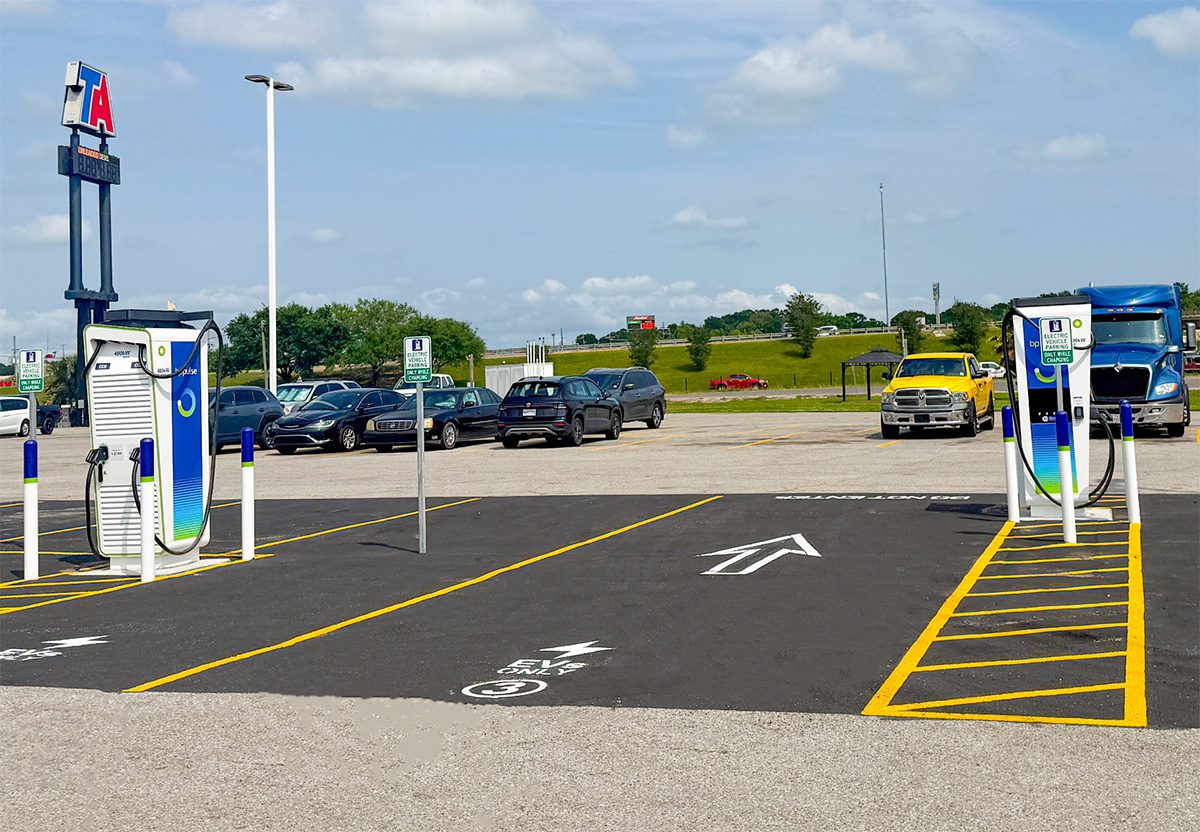
The article describes the deployment of high-power public DC fast-charging infrastructure rather than a vehicle battery innovation per se. From an engineering standpoint, the relevant technical core is the interaction between 400 kW class chargers and EV battery packs under high-rate charging conditions. The battery technology implications are driven by the need to accept very high charge power safely while maintaining cycle life, thermal stability, and acceptable charge time.
Given the charging power level and current market composition, the most plausible pack chemistries for vehicles that can meaningfully utilize these stations are:
- LFP (Lithium Iron Phosphate) for mass-market EVs prioritizing safety and cycle life
- NMC/NCA-class lithium-ion chemistries for higher energy density and longer-range vehicles
- Solid-state remains largely developmental and is not yet the dominant assumption for public 400 kW infrastructure compatibility
1) Assumed Cell Chemistry and Intrinsic Limitations
1.1 Most Likely Chemistry for 400 kW Public Charging: NMC and LFP
A 400 kW charger does not imply that every connected vehicle will charge at 400 kW. Actual delivered power is constrained by:
- pack voltage architecture
- cell chemistry
- cell internal resistance
- BMS current limits
- state of charge (SOC)
- cell temperature window
- vehicle-side thermal removal capacity
For current production EVs:
- NMC/NCA cells are typically the chemistry most capable of sustaining higher specific power at low-to-mid SOC due to higher nominal voltage and generally better low-temperature charge acceptance than LFP, though still constrained by lithium plating risk.
- LFP cells are increasingly common, especially in cost-sensitive platforms. They offer strong thermal robustness and long cycle life, but their lower nominal voltage and poorer low-temperature kinetics make them more restrictive under extreme fast charging.
1.2 LFP Intrinsic Limitations
LFP has several important constraints under fast charging:
- Lower cell voltage plateau (~3.2 V nominal) means more series cells are required for a given pack voltage.
- Lower energy density increases pack mass and volume, which indirectly worsens thermal inertia and packaging efficiency.
- Reduced low-temperature charge acceptance because lithium-ion diffusion through LFP particles and electrolyte transport both degrade at low temperatures.
- Charge curve flattening makes SOC estimation less precise near the upper region, increasing reliance on the BMS for conservative tapering.
- High-rate charging at low temperature elevates lithium plating risk despite LFP’s generally safer thermal profile.
In practice, LFP can tolerate abuse better thermally, but it often cannot exploit the full potential of 400 kW charging without aggressive thermal conditioning.
1.3 NMC Intrinsic Limitations
NMC-based cells generally support better energy density and often better fast-charge performance than LFP, but they introduce their own engineering constraints:
- Higher thermal sensitivity than LFP
- More pronounced degradation at elevated temperature
- Nickel-rich variants are more susceptible to calendar aging and microcrack-driven impedance rise
- Fast charging accelerates SEI growth and lithium plating, especially as SOC approaches the upper knee of the voltage curve
- Higher internal heat generation at high C-rate due to both ohmic and polarization losses
Thus, NMC is often the chemistry that can better utilize high charging power, but it requires more sophisticated thermal and electrochemical management.
1.4 Solid-State: Theoretical Advantages, Practical Readiness Constraints
Solid-state batteries are often discussed in the context of ultra-fast charging, but current limitations remain decisive:
- Interfacial impedance between solid electrolyte and electrodes can be high
- Stack pressure requirements complicate module design
- Dendrite suppression is not resolved universally across chemistries
- Manufacturing maturity and defect tolerance remain limited
- Thermal propagation behavior is not yet proven at automotive scale
If solid-state were broadly deployed, 400 kW charging could become more viable, but today it should not be assumed as the baseline chemistry for these charging sites.
2) Theoretical Thermal Management Challenges
2.1 Why 400 kW Charging Is a Thermal Problem First
At 400 kW, the battery is not merely “receiving energy”; it is operating as a high-power electrochemical reactor. Heat generation rises with:
- stack current squared times resistance: ( I^2R )
- electrochemical overpotential losses
- concentration polarization
- entropic heat, which can be either exothermic or endothermic depending on SOC and chemistry
Even if average pack power is limited by voltage rise and tapering, peak thermal loads during the constant-current phase can be severe.
2.2 Liquid Cooling Plate Design Constraints
A 400 kW-capable pack generally requires very effective liquid cooling, typically via:
- cold plates beneath or between modules
- direct refrigerant cooling in advanced architectures
- high-flow glycol-water loops
- well-controlled coolant distribution manifolds
Key engineering issues include:
Thermal resistance stack-up
The total thermal path includes:
- jellyroll or prism stack to cell can
- cell can to thermal interface material
- TIM to cold plate
- cold plate to coolant boundary layer
Any interface resistance increases cell-to-cell temperature spread, which becomes critical under fast charging.
Non-uniform flow distribution
In manifolded liquid plates, coolant maldistribution creates:
- hot spots at the inlet end
- degraded heat transfer near stagnant regions
- pack-to-pack variability in allowable charge power
Pressure drop vs. heat transfer tradeoff
Increasing fin density or microchannel complexity improves heat transfer but also raises:
- pump power
- manufacturing cost
- clogging risk
- reliability sensitivity
2.3 Thermal Gradients and Cell Balancing Implications
Fast charging requires not just low average pack temperature, but low thermal gradient across the pack. Large gradients create:
- uneven current acceptance
- local overpotential differences
- early onset of lithium plating in colder cells
- accelerated aging in hotter cells
The BMS may reduce charge power to protect the worst-performing cell, meaning the entire pack is limited by a single thermal bottleneck. For large DC fast-charge sessions, a uniform cell temperature window is often more important than absolute maximum cooling capacity.
2.4 Tab Cooling vs. Surface Cooling
Surface cooling
Most common in today’s EV packs, especially with pouch or prismatic cells. Advantages:
- mechanically simple
- easier to scale
- compatible with existing pack architectures
Limitations:
- heat must travel from the electrochemically active region to the cell surface
- center-of-cell heat rejection can be slow in thick electrodes or large-format cells
- temperature gradients through the cell thickness can be substantial at high C-rates
Tab cooling
More advanced and often more effective for high-power charging because the tabs are current collection hot spots and can also act as localized heat-collection features.
Advantages:
- can remove heat closer to the current path and internal resistive loss source
- reduces peak tab temperature, which is often a local degradation initiator
- can help suppress current concentration effects
Limitations:
- more complex design and manufacturing
- sealing, insulation, and reliability challenges
- difficult integration with high-voltage safety architecture
- may not sufficiently address volumetric heat generation in the cell core
2.5 Implications for 400 kW Charging Sites
The charging site itself does not cool the battery, but it determines whether vehicles can sustain high power long enough to matter. Vehicles with:
- advanced preconditioning
- robust liquid thermal loops
- large coolant-to-cell contact area
- low-impedance cell designs
will extract far more benefit from these stations than vehicles with passive or lightly cooled pack architectures. In other words, charger power is only useful if the pack can absorb heat at a comparable rate.
3) Fast-Charging Constraints: Electrochemical and Transport Limits
3.1 Ionic Conductivity and Transport Bottlenecks
At high C-rates, charge acceptance is limited by:
- electrolyte ionic conductivity
- lithium-ion diffusion through the separator and porous electrodes
- solid-state diffusion within active material particles
- charge-transfer kinetics at the electrode/electrolyte interface
As current increases, concentration gradients develop:
- lithium ions deplete near the electrode surface
- local overpotential rises
- the electrode surface potential can drop below the lithium plating threshold on graphite anodes
This is the primary reason that the battery cannot simply accept 400 kW continuously. The limiting factor is not the charger’s capability, but the pack’s electrochemical transport physics.
3.2 Lithium Plating Risk
Lithium plating occurs when metallic lithium deposits on the anode instead of intercalating into graphite. It is promoted by:
- low anode temperature
- high charge current
- high SOC
- poor mass transport
- high interfacial resistance
- insufficient preconditioning
Plating is especially dangerous because it can lead to:
- irreversible capacity loss
- impedance increase
- dendritic growth
- separator damage
- accelerated degradation and safety risk
3.3 Why High Power Becomes Unusable Near High SOC
Even if a vehicle can initially accept very high power at low SOC, charging power must taper because:
- cathode potential rises as SOC increases
- anode potential approaches the lithium plating threshold
- internal resistance increases with SOC and temperature rise
- BMS safety margins narrow
Thus, the headline 400 kW figure usually applies only in a narrow SOC and temperature window, often at low SOC and warm pack conditions.
3.4 Chemistry-Specific Fast-Charge Behavior
LFP
- generally safer thermally
- often more tolerant of cycle life abuse
- but can be more limited by low-temperature plating and lower conductivity at suboptimal temperatures
- needs strong thermal conditioning to approach high-rate acceptance
NMC
- can often accept higher power in the optimal thermal window
- but degrades faster if pushed aggressively
- more sensitive to temperature-induced side reactions and aging
Solid-state
- potentially higher charge rates in principle
- but interfaces and dendrite-like failure modes remain unresolved in practice
- not yet a universally deployable solution for mainstream ultra-fast charging
4) Engineering Interpretation of the Charging Network Deployment
The deployment of 400 kW CCS/NACS stations at highway-adjacent travel centers implies a strategic assumption: a growing subset of vehicles will have pack designs capable of sustained high-rate DC charging, at least under favorable conditions. However, from a battery engineering perspective, the utility of such infrastructure is bounded by:
- pack thermal rejection capability
- cell chemistry selection
- electrode loading and separator design
- BMS power taper strategy
- preconditioning effectiveness
- ambient temperature and route profile
This means charging infrastructure expansion is only one half of the fast-charging equation. The other half is the battery pack’s ability to absorb charge without exceeding electrochemical or thermomechanical limits.
5) Bottom-Line Technical Assessment
5.1 Most Plausible Battery Technology Context
For vehicles utilizing these stations, the most realistic chemistries are NMC and LFP, with NMC more likely to exploit high peak power and LFP more likely to be constrained by low-temperature and high-current limitations.
5.2 Main Thermal Bottleneck
The limiting factor at 400 kW is not simply “cooling capacity,” but thermal uniformity, interface resistance, and heat extraction from the cell core under large current density.
5.3 Main Fast-Charge Bottleneck
The fundamental electrochemical constraint is lithium plating risk driven by ionic transport limits and overpotential, especially at low temperature and high SOC.
5.4 Practical Implication
A 400 kW charger can shorten dwell times substantially, but only for vehicles whose packs are engineered with:
- low impedance cells
- aggressive liquid cooling
- robust thermal preconditioning
- BMS algorithms that tightly manage plating risk and variable charge taper
If you want, I can also turn this into a teardown-style battery pack assessment template with sections like cell format, cooling topology, busbar architecture, BMS limits, and probable charge curve behavior.