Technical Interpretation of the Electrified RTG Crane Architecture
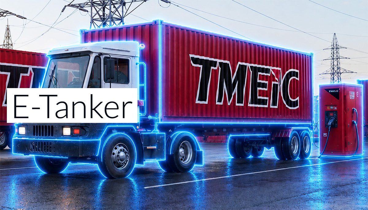
The disclosed TMEIC E-Tanker concept is best interpreted as a containerized, modular battery-buffered DC energy logistics system for port electrification, rather than a simple “mobile charger.” The architecture appears intended to decouple RTG crane electrification from immediate grid reinforcement by combining:
- a mobile lithium-ion energy storage unit,
- replaceable/high-energy battery blocks on or near the crane side,
- a charging station for staged replenishment, and
- an FMS (fleet management system) for dispatch and energy scheduling.
From an engineering standpoint, this is essentially a distributed energy transfer problem under harsh duty-cycle constraints: high peak power, rapid turnaround, limited footprint, salt-fog/corrosion exposure, and tight operational uptime requirements.
Because the article does not specify chemistry, power density, or thermal architecture, the following analysis infers the most plausible battery technology envelope used in such a port-cargo application.
1) Assumed Cell Chemistry and Intrinsic Limitations
Most likely chemistry: LFP, or a high-safety variant of NMC
For RTG crane electrification, the most probable chemistry is LFP (LiFePO₄), with a secondary possibility of low-to-mid nickel NMC if energy density constraints dominate. For port equipment, chemistry selection is usually governed by:
- cycle life,
- abuse tolerance,
- thermal stability,
- long dwell operation,
- low maintenance burden,
- total cost of ownership.
Why LFP is the default assumption
LFP is often favored in industrial electrification because it offers:
- high thermal stability and comparatively benign oxygen-release behavior,
- excellent cycle life under deep cycling,
- lower runaway propagation risk,
- lower cobalt dependency and reduced supply-chain volatility.
However, LFP has intrinsic limitations that matter here:
- Lower gravimetric and volumetric energy density than NMC.
- Reduced low-temperature performance: impedance rises sharply in cold conditions, increasing charge acceptance limits and ohmic loss.
- Flat OCV-SOC curve: precise SOC estimation is more difficult under dynamic load; voltage alone is a weak state estimator.
- Higher current requirement for the same power due to lower nominal voltage per pack energy target, increasing conductor, busbar, contactor, and thermal stress.
For RTG cranes, the mass penalty of LFP is less problematic than in road vehicles, but it can still affect:
- containerized system footprint,
- crane-mounted battery block mass,
- axle loading of transport units,
- and thermal inertia during repeated high-power transients.
If NMC is used
If the system prioritizes compactness and higher energy density, an NMC-based architecture is plausible. But NMC is less forgiving in port duty cycles because:
- thermal runaway onset is more severe,
- nickel-rich variants have stronger impedance growth under high SOC and elevated temperature,
- fast-charging windows are narrower,
- calendar aging accelerates at high SOC and high temperature.
In a containerized system exposed to high ambient temperature, salt corrosion, and repetitive high C-rate operation, LFP is the more conservative engineering choice.
Why solid-state is unlikely
A solid-state assumption is not credible for this deployment given current industrial maturity. While solid-state promises improved safety and potentially higher energy density, it still faces:
- stack pressure sensitivity,
- interface resistance management,
- dendrite suppression challenges at high practical current densities,
- manufacturability and cost barriers,
- uncertain field reliability in large-format industrial packs.
For a port electrification rollout where uptime and maintainability are paramount, solid-state would be atypical unless the announcement were explicitly about a pilot demonstrator.
2) Thermal Management Challenges in a Containerized Mobile Charging System
System-level thermal problem definition
The E-Tanker concept likely combines:
- one or more stationary lithium-ion packs inside the 40-foot container,
- a charge/discharge interface with the crane battery blocks,
- and high daily throughput with repeating charge pulses.
This creates a thermal management challenge that is more complex than ordinary EV charging because the system must manage both charge heat and discharge heat, often with minimal rest periods.
The main loss mechanisms are:
- ohmic heating: ( I^2R ) in cells, interconnects, contactors, and cables,
- entropic heat during charge/discharge,
- pack-level imbalance heating from cell mismatch,
- power electronics losses in DC/DC conversion and switching devices.
At high C-rate, heat is not only a safety issue; it is also a direct limiter of:
- charge acceptance,
- usable power,
- lifetime,
- and balancing effectiveness.
Likely cooling architecture: liquid cooling plate or cold plate system
For a commercial port application, the most probable thermal design is liquid-cooled cold plates beneath or adjacent to cell modules. Air cooling alone is generally inadequate for high energy throughput in a containerized industrial pack unless power density is modest.
Why liquid cooling is likely required
A liquid system provides:
- higher heat flux removal,
- more uniform module temperature,
- better control of local hotspots,
- better scalability for containerized enclosures.
But cold-plate integration introduces several engineering constraints:
- contact resistance between cell/module and plate,
- coolant channel uniformity,
- pressure drop vs. pumping power tradeoff,
- leak risk and maintenance complexity,
- compatibility with marine/industrial corrosion conditions.
Thermal gradients as a hidden reliability driver
In large modules, the core problem is rarely average temperature; it is temperature delta across the pack.
If cells in one region run 5–10°C hotter than others, the consequences include:
- accelerated SEI growth in the hot region,
- faster electrolyte decomposition,
- SOC imbalance due to temperature-dependent capacity and resistance,
- local loss of cyclable lithium,
- and earlier onset of cell divergence.
A containerized system can easily develop gradients from:
- inlet-to-outlet coolant rise,
- uneven module loading,
- solar gain on the container shell,
- localized power electronics heating,
- and asymmetric cable routing.
A good design will therefore seek not just heat removal capacity but thermal uniformity, often targeting very tight inter-cell temperature spread.
Tab cooling vs. surface cooling
This application raises an important mechanical-thermal distinction.
Surface cooling
Surface cooling acts on the cell can or module face, extracting heat through:
- bottom plates,
- side plates,
- or direct contact with a thermal interface material.
Advantages:
- simpler implementation,
- scalable to module arrays,
- compatible with prismatic or pouch packaging.
Limitations:
- heat must conduct through the cell stack to the cooled surface,
- internal jelly-roll or electrode-stack gradients can remain significant,
- end-of-pack hotspots may persist if current collection is concentrated.
Tab cooling
Tab cooling is particularly relevant for pouch cells or systems with current concentrated at the tabs/end terminals.
Advantages:
- directly targets one of the strongest resistive heating locations,
- useful for fast charge where current collection becomes a bottleneck,
- can reduce local thermal runaway likelihood near interconnects.
Limitations:
- mechanically complex,
- often insufficient alone because the bulk cell still generates distributed heat,
- difficult to implement at scale in ruggedized industrial modules.
For RTG crane battery blocks, surface/cold-plate cooling is the more likely primary strategy, with tab-region thermal reinforcement only if the design uses pouch cells or high-current prismatic terminations. If the blocks are high-power and compact, the thermal design may combine end-terminal cooling and baseplate cooling.
Environmental challenges unique to port duty
Ports impose additional thermal constraints beyond pure electrical load:
- ambient heat and radiant loading from concrete, steel structures, and solar exposure,
- salt mist and humidity, which can degrade pumps, fittings, heat exchangers, and connectors,
- dust and particulate contamination, which reduces heat exchanger efficiency,
- containerized enclosure ventilation constraints, especially if the system is housed in a 40-foot ISO container.
Thus, the thermal solution likely requires:
- sealed coolant loops,
- corrosion-resistant manifolds,
- redundant fans or liquid-to-air exchangers,
- and robust thermal monitoring at cell-group granularity.
3) Fast-Charging Constraints and Electrochemical Limits
The fundamental fast-charge bottleneck: lithium-ion transport
Fast charging in lithium-ion systems is constrained not by charger nameplate power alone, but by ion transport kinetics and charge-transfer limits inside the electrode stack.
At high C-rate, several processes become limiting:
- electrolyte ionic conductivity and concentration polarization,
- solid-state diffusion of Li within active particles,
- interfacial charge-transfer resistance,
- SEI film impedance,
- and pack-level voltage sag from high current.
In practical terms, the battery can only accept charge as quickly as lithium ions can move through:
- the electrolyte,
- the porous electrode,
- the active particle structure,
- and the interfacial reaction sites.
Lithium plating risk at high C-rate
The most severe fast-charge failure mode is metallic lithium plating on the graphite anode, especially when charging at low temperature, high SOC, or elevated impedance.
Plating risk increases when:
- anode potential approaches 0 V vs. Li/Li⁺,
- current density exceeds the anode’s insertion capability,
- temperature is low,
- or the pack is already near high SOC.
This matters because plated lithium can:
- reduce cyclable lithium inventory,
- form dendritic structures,
- create internal shorts,
- accelerate SEI growth,
- and permanently degrade capacity.
For industrial equipment like RTG cranes, fast charge may be driven by operational downtime windows, which can tempt aggressive charge profiles. But the battery management system must enforce conservative limits based on:
- cell temperature,
- SOC window,
- internal resistance,
- prior duty cycle,
- and cell-to-cell dispersion.
C-rate implications for port equipment
If the mobile system is intended to charge battery blocks quickly between crane cycles, the effective C-rate can be substantial. Even if average energy throughput is moderate, the peak recharge rate may be high due to the need to preserve terminal uptime.
This creates three constraints:
1. Thermal rise under fast charge
Fast charge increases internal heat generation approximately with ( I^2R ). Without excellent thermal extraction, cell temperature ramps quickly, forcing the BMS to taper current.
2. Polarization-induced voltage overshoot
At high current, terminal voltage rises due to internal resistance and diffusion polarization. The charger may hit upper voltage limits before the cell is fully charged, reducing usable capacity and creating a non-linear charge curve.
3. Degradation acceleration
Aggressive charge rates increase:
- SEI thickening,
- loss of lithium inventory,
- mechanical particle cracking,
- electrode swelling in some chemistries,
- and long-term impedance growth.
Chemistry-specific fast-charge performance
LFP
LFP is thermally safer, but not inherently fast-charge optimal. Its practical limitations include:
- moderate rate capability compared with some high-power NMC formulations,
- low-temperature charge constraints,
- poorer SOC observability due to the flat voltage profile,
- and possible lithium plating under cold/high-current conditions.
NMC
NMC can offer better energy density and potentially strong power performance, but fast charge must be tightly managed due to:
- thermal sensitivity,
- stronger aging penalties at high SOC and high temperature,
- and the same anode-plating risks if graphite is the negative electrode.
Solid-state
In principle, solid-state could improve charge safety, but real-world high-current limits remain constrained by:
- interface impedance,
- pressure management,
- and current density uniformity.
Engineering Assessment of the E-Tanker Concept
What the architecture is solving
The core technology is not just battery electrification; it is energy logistics decoupling for port assets. The system attempts to solve:
- grid connection bottlenecks,
- yard redesign constraints,
- crane retrofit downtime,
- and operational continuity.
Remaining technical risk centers
For an engineering audience, the main unresolved design risks are likely:
- pack thermal uniformity at high duty cycle,
- coolant manifold reliability in corrosive environments,
- fast-charge taper behavior under real crane load,
- SOC estimation accuracy under flat-voltage chemistry,
- and cell aging under repetitive high-power cycles.
Most probable technology conclusion
If implemented as implied, the system is most likely based on:
- LFP cylindrical or prismatic modules for safety and cycle life, or
- industrial NMC if energy density is prioritized.
However, regardless of chemistry, success depends on:
- high-uniformity liquid cooling,
- careful current derating at low temperature and high SOC,
- robust BMS controls to prevent lithium plating,
- and pack-level thermal design that minimizes gradients rather than merely lowering average temperature.
Bottom-Line Engineering View
The E-Tanker is best understood as a containerized battery exchange/charging infrastructure platform optimized for port electrification. Its technical feasibility hinges less on the mobility of the charger and more on whether the battery blocks can tolerate:
- repeated high C-rate charging,
- harsh thermal environments,
- limited cooling volume,
- and long-life industrial cycling.
From a battery engineering perspective, the dominant constraints are:
- Chemistry selection: LFP is most probable due to safety and cycle life, but it sacrifices energy density and low-temperature charge performance.
- Thermal management: liquid cold plates are likely mandatory; thermal gradients and hotspot suppression are critical.
- Fast charging: the system must avoid lithium plating by controlling current, temperature, and SOC window, especially in a port environment where uptime pressures can encourage aggressive charging.
If you’d like, I can also provide this as a failure-mode-and-effects analysis (FMEA) or a pack architecture teardown checklist for the same concept.