Engineering Interpretation of the Deployment
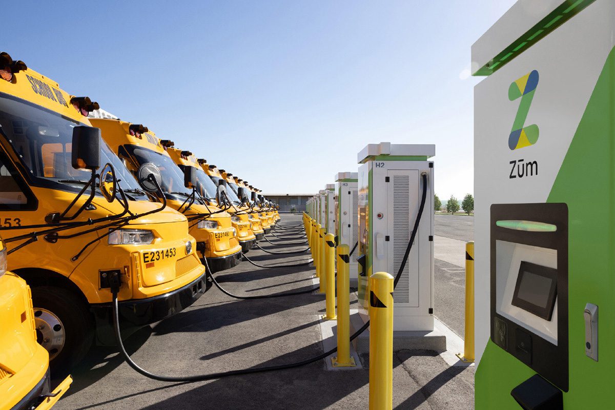
The article describes a fleet-scale electric school bus deployment with bidirectional charging (V2G). From an engineering standpoint, the relevant technical content is not the fleet announcement itself, but the implications of using large-format traction batteries as both mobility assets and stationary grid resources.
For a school bus V2G program, the battery system must tolerate:
- Repeated daily cycling beyond pure traction duty
- Long dwell-time connected charging
- Grid-support dispatch events at elevated SOC windows
- Thermal and electrochemical stress from high-power charge/discharge transients
- Calendar aging impacts due to frequent partial cycling and high SOC parking
The core battery technology is not explicitly stated in the article, so chemistry must be inferred from current school-bus market practice and V2G safety constraints.
1. Assumed Cell Chemistry and Intrinsic Limitations
Most likely chemistry: LFP
For school bus applications, the most probable chemistry is lithium iron phosphate (LFP) rather than NMC, for several reasons:
- High cycle life under daily commercial duty
- Superior thermal stability and lower runaway propagation risk
- Lower cost and reduced dependence on nickel/cobalt supply chains
- Good abuse tolerance, important for school transportation and fleet insurance profiles
While some bus OEMs still use NMC for higher energy density, the combination of school-bus duty cycle + V2G + grid service + cost sensitivity strongly favors LFP.
Why LFP is attractive here
LFP’s practical advantages in this deployment include:
- Longer usable cycle life at moderate depth-of-discharge
- Better thermal runaway onset temperature than layered oxide cathodes
- More stable voltage plateau, simplifying battery management for fleet use
- Better tolerance to frequent dwell-at-high-SOC operation than many high-Ni cathodes
Intrinsic limitations of LFP
However, LFP has important electrochemical and pack-level limitations:
Lower gravimetric and volumetric energy density
Compared with NMC, LFP has:
- Lower Wh/kg
- Lower Wh/L
For buses, this typically means:
- Higher pack mass for equivalent range
- Larger floor or roof packaging volume
- Greater structural load on chassis and suspension
- Potentially increased cooling-system surface area requirement
Flat OCV-SOC curve
LFP’s open-circuit voltage profile is relatively flat over much of its SOC window. That creates BMS challenges:
- SOC estimation is less observable from terminal voltage alone
- Coulomb counting and model-based observers become mandatory
- SOH drift can accumulate if calibration is infrequent
- V2G dispatch control must account for uncertainty in available energy headroom
Poor low-temperature charge acceptance
LFP is especially sensitive to low-temperature charging:
- Lithium-ion diffusivity in graphite anode and electrolyte transport decrease with temperature
- Internal resistance rises sharply in cold conditions
- Fast charging at low temperature substantially increases lithium plating risk
This is a major constraint for school buses because fleets often charge overnight and may start charging while the pack is cold.
Moderate-rate performance limitations
Although LFP is safer, it is not immune to:
- Increased polarization at high C-rate
- Capacity loss if repeatedly charged and discharged at high current
- Greater heat generation during fast charge due to ohmic and entropic effects
Why not NMC as the default assumption?
NMC would offer:
- Higher energy density
- Potentially lower pack mass
But for this use case, NMC is less attractive because:
- Thermal runaway margin is narrower
- Material cost and supply-chain exposure are higher
- High-SOC storage accelerates degradation more aggressively
- V2G operation increases cumulative cycle count and time spent at elevated SOC
That said, if the buses prioritize range over cost and thermal robustness, an NMC variant remains possible. In that case, thermal and aging constraints become more severe than with LFP.
Solid-state is unlikely
A solid-state battery assumption is not credible for this 2026 fleet deployment unless explicitly stated. Reasons:
- Manufacturing maturity remains limited for large commercial bus packs
- Cost and supply chain are not yet fleet-optimal
- Fast-charge claims and V2G reliability requirements favor mature liquid-electrolyte systems
- Field serviceability in fleet operations is currently better suited to conventional Li-ion
2. Thermal Management Challenges in a V2G School Bus Pack
Why V2G changes the thermal problem
A school bus battery pack in a V2G architecture is not just a storage device; it becomes a bidirectional power electronics load subject to:
- Charging during depot dwell
- Discharging to the grid during peak events
- Potentially multiple current reversals per day
- Long periods at high state of charge
This creates more severe thermal complexity than traction-only duty because heat is generated in both:
- Charge mode
- Discharge mode
and at both:
- Cell internal resistance
- Module interconnects, contactors, busbars, and power electronics
Liquid cooling plate design considerations
For bus-scale packs, liquid cold plates are the dominant architecture. Key design variables include:
Coolant path layout
The cold plate must maintain:
- Low thermal resistance from cell-to-coolant
- Uniform coolant flow distribution across long pack modules
- Minimal pressure drop to reduce pump parasitics
Poor manifold design can create:
- Hot spots at downstream cells
- Localized temperature rise at end-of-run channels
- Uneven aging across parallel cell groups
Plate-cell interface conductivity
Effective heat extraction depends on:
- TIM thermal conductivity
- Bond-line thickness
- Contact pressure uniformity
- Mechanical compliance under vibration and thermal expansion cycles
If interface resistance is too high, the cold plate becomes a bottleneck even if coolant flow is adequate.
Parallel vs. serpentine flow
- Serpentine flow offers simpler plumbing but larger inlet-to-outlet coolant temperature rise, increasing gradients along pack length.
- Parallel flow improves thermal uniformity but requires careful hydraulic balancing to avoid maldistribution.
For a large bus pack, thermal uniformity is usually more important than minimizing manifold complexity.
Thermal gradients across large-format cells
School bus packs often use large-format prismatic cells or large modules. These are prone to internal temperature gradients because:
- Heat generation is volumetrically distributed
- Current collectors and tabs create edge concentration effects
- Center regions can be thermally insulated relative to surfaces
Consequences of gradients include:
- Non-uniform aging
- SOC imbalance between cells or cell regions
- Differential expansion and mechanical fatigue
- Increased local overpotential, especially under fast charge
A typical failure mode is that the cell core remains hotter for longer than the case surface, meaning surface temperature sensors can underestimate peak core temperature.
Tab cooling vs. surface cooling
The article does not specify the pack architecture, but a high-power V2G bus pack raises the question of tab cooling versus surface cooling.
Surface cooling
Most common in current EV packs:
- Coolant plate removes heat from the cell face
- Easier to manufacture at module scale
- Good for prismatic and pouch cells
Limitations:
- Thermal path from jelly roll or stacked electrode core to surface can be long
- Tab hotspots may remain poorly controlled
- Surface temperature may lag internal temperature rise
Tab cooling
Tab cooling can be advantageous because:
- Tabs are often local current-density hotspots
- Heat can be extracted closer to the site of resistive generation
- Particularly useful in high-power, high-C-rate operation
But tab cooling is harder to implement because:
- Electrical isolation requirements are stricter
- Thermal interface at the tab-pack transition is complex
- Mechanical fatigue at tab welds can be exacerbated by thermal cycling
- Manufacturing and service complexity increase
Engineering implication for V2G buses
For frequent bidirectional operation, a hybrid thermal architecture is ideal:
- Surface cooling for bulk heat extraction
- Localized tab or end-plate cooling for hotspot suppression
- Close-loop coolant control tied to power limits and ambient conditions
Cooling system control strategy
For a fleet bus, thermal management is not passive; it is an energy management control problem. The system must coordinate:
- Battery temperature
- Charger setpoint
- Grid dispatch schedule
- Ambient temperature
- Vehicle dwell time
- Battery SOC window
To preserve battery life, the BMS should limit:
- Fast charge rates when cell temperature is low
- High discharge power during elevated pack temperatures
- Charging to 100% SOC unless necessary for duty requirements
3. Fast-Charging Constraints and Electrochemical Limits
Process limitations at high C-rates
Fast charging a lithium-ion bus pack is constrained by the ability of the cell to transport ions and insert lithium into the graphite anode without plating.
The key bottlenecks are:
- Ionic conductivity of the electrolyte
- Lithium-ion diffusion in porous electrodes
- Charge-transfer kinetics at the electrode/electrolyte interface
- Solid-state diffusion in active material particles
- Ohmic resistance in current collectors and tabs
As C-rate increases, cell overpotential rises. If the anode potential drops too close to 0 V vs Li/Li+, metallic lithium can deposit.
Lithium plating risk
Lithium plating becomes more likely under the following conditions:
- High charge current
- Low cell temperature
- High SOC, especially near the upper end of charge
- Elevated internal resistance due to aging
- Non-uniform current distribution in large-format cells
This is especially relevant for fleet buses because they may be:
- Charged quickly between routes
- Charged overnight in cold ambient conditions
- Recharged after V2G discharge events if battery SOC is managed aggressively
Why plating is dangerous
Lithium plating causes:
- Loss of cyclable lithium
- Capacity fade
- Increased impedance
- Potential dendrite formation and internal short risk
It is not merely a performance problem; it is a safety and reliability problem.
Ionic conductivity limitations
Electrolyte ionic conductivity decreases with:
- Lower temperature
- Higher tortuosity in electrode pores
- Increased salt depletion near the anode surface at high current
At high C-rates, concentration polarization becomes significant. In practical terms:
- The electrolyte near the anode becomes lithium-ion depleted
- The anode overpotential rises
- Charge acceptance falls
- The BMS must taper current earlier than operators might expect
LFP-specific fast-charge behavior
If the buses use LFP, fast charging is somewhat more forgiving thermally than NMC, but still constrained by the graphite anode and electrolyte transport. LFP does not eliminate lithium plating risk because plating is often determined more by:
- Anode kinetics
- Temperature
- Current density
- Cell design
than by cathode chemistry alone.
Pack-level current distribution issues
Large bus batteries have additional fast-charge challenges beyond cell chemistry:
- Current non-uniformity across parallel strings
- Busbar resistance imbalance
- Connector contact resistance variation
- Module-level temperature spread
- BMS tolerance stack-up
These effectors can create the paradox where the whole pack is within allowable charge current, but some cells experience locally excessive current density.
4. Implications for Bidirectional Charging Operation
Cycling profile differs from a normal EV
A bus used for V2G experiences a mixed duty cycle:
- Morning discharge for route operation
- Midday or depot charging
- Grid-support discharge during peak hours
- Overnight recharge
This is not equivalent to simple vehicle charging, because the pack sees:
- More equivalent full cycles per calendar day
- More high-SOC residence time
- More transient power events
- More thermal cycling
Battery aging mechanisms likely to dominate
For such a fleet, dominant degradation modes are likely to include:
- Loss of lithium inventory from SEI growth and plating
- Impedance increase from electrode aging and contact degradation
- Calendar aging from high SOC exposure
- Mechanical degradation from repeated expansion/contraction and vibration
- Thermal nonuniformity-driven cell imbalance
Engineering target for fleet optimization
The pack should be controlled to maximize:
- Usable cycle life
- Thermal uniformity
- Dispatchable energy
- Minimum auxiliary cooling energy
rather than maximizing absolute energy throughput.
5. Bottom-Line Technical Assessment
From a battery engineering perspective, this deployment most likely relies on LFP-based large-format lithium-ion battery packs optimized for safety, durability, and fleet economics rather than maximum energy density.
The main technical risks are:
- Thermal non-uniformity in long bus packs, especially under V2G power reversal
- Fast-charge/plating limitations at low temperature or high SOC
- Aging acceleration due to frequent grid-service cycling and high SOC parking
- Pack-level current imbalance in high-power bidirectional operation
The success of the program will depend less on the nominal battery capacity and more on:
- Thermal architecture quality
- BMS sophistication
- Charge/discharge derating logic
- Cell matching and module balance
- Control of SOC windows during grid participation
If you want, I can also provide this as a teardown-style engineering memo with sections for cell format, pack architecture, BMS strategy, and failure modes.