Technical Assessment of Scania’s Under-Cab Battery Module
Scania’s under-cab battery architecture is primarily a packaging and system-integration innovation rather than a new electrochemical breakthrough. The article strongly suggests an engineering optimization aimed at truck-level constraints: maximizing usable energy while preserving payload, chassis flexibility, and charging-operational compatibility. From a battery-engineering standpoint, this implies a conventional high-volume EV cell chemistry packaged into a structurally constrained heavy-duty pack, likely optimized for durability, cost, and fast-charge operation rather than absolute gravimetric energy density.
1) Likely Cell Chemistry and Intrinsic Limitations
Probable chemistry: LFP or LFP-dominant high-volume heavy-duty architecture
Given the application domain—heavy-duty trucks, central under-cab packaging, emphasis on usable capacity, payload preservation, and cost-efficient charging strategy—the most probable chemistry is LFP (LiFePO₄) or an LFP-dominant variant. This is especially plausible because:
- Heavy-duty fleets prioritize cycle life, thermal robustness, and low total cost of ownership.
- LFP has superior abuse tolerance relative to nickel-rich chemistries.
- The packaging emphasis suggests system-level efficiency is more important than maximizing Wh/kg at cell level.
A less likely but still possible option is high-nickel NMC in a carefully managed pack, though the truck use case and the stated capacity/packaging tradeoffs make LFP more consistent with the commercial logic. Solid-state is very unlikely in a global sales rollout context because that would imply manufacturing maturity and supply chain readiness not indicated by the article.
Intrinsic limitations if LFP
If the module uses LFP, the key limitations are well known:
- Lower specific energy than NMC: volumetrically and gravimetrically, LFP requires more pack mass and/or volume for a given kWh.
- Lower cell voltage plateau and flatter OCV-SOC curve: this complicates SOC estimation, especially under load and after rest.
- Poorer low-temperature charge acceptance: lithium-ion diffusion in graphite anodes becomes rate-limiting, while LFP cathode kinetics are also less favorable in cold operation.
- Reduced fast-charging headroom versus nickel-rich systems when pack thermal control is constrained.
- More substantial volumetric penalty: relevant here because the under-cab envelope is geometrically constrained by cabin structure, steering hardware, crash load paths, and service access.
Intrinsic limitations if NMC
If the module instead uses NMC, the challenges shift:
- Higher thermal sensitivity and tighter management of local hot spots.
- Greater concern for cathode degradation, oxygen release at elevated temperatures, and accelerated calendar aging at high SOC.
- Reduced robustness for repeated high-power charging unless the pack is aggressively cooled and derated.
For heavy-duty duty cycles, NMC would demand a more sophisticated thermal design and more conservative charging envelopes than LFP.
2) Under-Cab Packaging: Structural and Thermal Integration Constraints
Packaging-driven cell and module architecture
An under-cab battery module is not a simple “wider pack under the floor.” It is a structural packaging compromise that must coexist with:
- front-axle steering geometry,
- cab suspension travel,
- crash energy absorption zones,
- service access under tilting cab conditions,
- NVH isolation,
- ingress protection from road spray, debris, and salt.
This usually pushes the design toward a low-profile, large-footprint module with strong structural stiffening. Such geometry is thermally important because it influences the cooling path length and temperature field uniformity.
Implication for thermal gradients
A low-profile module under the cab often has nonuniform boundary conditions:
- The center of the pack may be more thermally insulated by surrounding structure.
- Edge cells/modules may see better convective exposure during vehicle motion.
- Local thermal asymmetry can arise due to coolant manifold placement, cabin substructure shadowing, and uneven heat rejection to underbody airflow.
As pack thickness reduces, the thermal engineer must balance:
- lower conduction path to a cold plate,
- against increased sensitivity to coolant distribution maliformation,
- and against local peak temperatures in cells at the geometric center of the module.
In practice, this is often where series-parallel cooling path design becomes more important than nominal coolant flow rate.
3) Theoretical Thermal Management Challenges
Liquid cooling plate design
For a truck pack designed around high usable energy and fast-charge readiness, liquid cooling is almost mandatory. The likely architecture would be one of the following:
- Direct bottom cold plate cooling
- Serpentine or parallel coolant channel cold plate
- Extruded aluminum cooling plate integrated with the module base
- In higher-end designs, dual-sided cooling or interleaved cooling rails
The main design challenge is reducing cell-to-cell and cell-to-coolant thermal resistance while maintaining manufacturability and leak integrity.
Key engineering variables include:
- coolant channel hydraulic diameter,
- Reynolds number and turbulence promotion,
- cold-plate flatness and contact pressure,
- TIM thickness and thermal conductivity,
- plate material selection and corrosion resistance,
- pressure drop vs. pump power.
Thermal gradient control
Fast-charging heavy-duty packs must limit temperature spread across the module. Even modest gradients can create uneven aging because degradation rate is highly temperature dependent. For lithium-ion cells:
- higher temperature accelerates SEI growth and electrolyte decomposition,
- lower temperature increases charge-transfer resistance and lithium plating risk,
- gradients create nonuniform SOC evolution and current sharing imbalance.
If one area of the pack reaches elevated temperature during MCS charging while another remains cooler, the cooler region may actually become the charge-limiting bottleneck due to plating risk, forcing global current derating.
Tab cooling vs. surface cooling
The article does not specify tab cooling, but for megawatt-class charge rates this becomes a relevant engineering question.
Surface cooling
Most current EV packs rely on surface cooling, typically through the module base. This is mechanically simpler, but for high C-rate operation it has limitations:
- Heat generated in the jelly roll has to conduct radially or laterally to the cooled face.
- Large-format cells can develop significant internal temperature gradients.
- The terminal region may run hotter than the cooled face, especially under high current.
Tab cooling
Tab cooling or direct terminal heat extraction can reduce local terminal heating and resistance rise during fast charge/discharge. This is particularly relevant because:
- current concentration at tabs and current collectors increases Joule heating,
- busbar, weld, and terminal resistance can become a nontrivial heat source,
- end-of-charge conditions can create localized heat accumulation even when average cell temperature is acceptable.
However, tab cooling adds complexity:
- more difficult dielectric isolation,
- more stringent mechanical tolerances,
- higher manufacturing cost,
- more complex serviceability.
For a rugged truck pack, the likely design is a hybrid thermal scheme: bulk surface cooling via cold plate, with highly optimized low-resistance busbar and tab design to minimize terminal hot spots rather than fully active tab cooling.
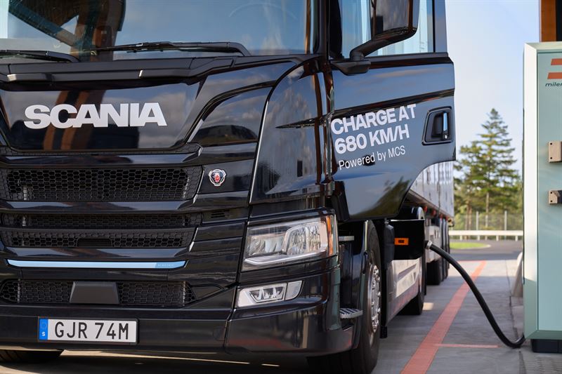
4) Fast-Charging Constraints and MCS Implications
Why charging strategy matters more than pure battery size
The article explicitly emphasizes charging strategy over maximum battery capacity. That is consistent with battery engineering reality: once a truck has sufficient energy for route coverage, the governing factor becomes energy replenishment rate per duty cycle, not just nominal pack size.
MCS-class charging introduces a different constraint regime than passenger EV fast charging:
- very high current levels,
- high thermal load in conductors, contactors, and interconnects,
- strong sensitivity to coolant performance,
- strict protection against lithium plating and cell-to-cell imbalance.
Ionic conductivity and transport limits
At elevated C-rates, performance is limited by coupled transport phenomena:
- electrolyte ionic conductivity,
- lithium-ion diffusion through porous electrodes,
- solid-state diffusion in active material particles,
- interfacial charge-transfer kinetics,
- separator transport resistance.
As current increases, concentration gradients build in the electrolyte. The local lithium-ion depletion near the anode surface increases overpotential. If overpotential becomes too large, the anode potential can approach 0 V vs. Li/Li⁺, enabling metallic lithium plating.
Lithium plating risk
Lithium plating is the critical safety and durability limit under high-power charging, especially if any of the following apply:
- low cell temperature,
- high SOC near the top end,
- aged cells with increased impedance,
- nonuniform current distribution,
- poor thermal rejection in center cells.
From a truck operator standpoint, the problem is not just catastrophic failure; it is throughput degradation. Even mild plating can:
- consume cyclable lithium,
- increase impedance,
- raise heat generation in future cycles,
- accelerate gas generation and swelling,
- create long-term capacity fade and imbalance.
LFP vs NMC fast-charging behavior
If this pack is LFP-based, it benefits from thermal stability but still faces anode-limited charge acceptance. LFP does not eliminate plating risk; it mainly improves thermal safety margin. If NMC-based, the same charge rate would impose additional cathode and thermal aging concerns.
System-level mitigation strategies
To support megawatt charging in a fleet environment, the pack would require a combination of:
- preconditioning to bring cells into the optimal temperature window,
- adaptive charge curves with strong tapering near high SOC,
- precise cell-voltage monitoring for early plating avoidance,
- low-resistance busbars and welds,
- robust coolant flow distribution to suppress local hot spots,
- possibly pack segmentation so that current distribution can be managed more granularly.
5) Range–Payload Tradeoff as an Electro-Mechanical Design Problem
The article frames the truck’s value proposition around preserving payload while offering up to 400 kWh usable capacity. That is not just a logistics feature; it reflects a fundamental electromechanical optimization.
Mass distribution and axle loading
Under-cab placement helps shift battery mass forward and low:
- lowers the center of gravity,
- reduces frame rail packaging conflicts,
- can improve axle load distribution,
- may free up the rear chassis for bodywork and mission-specific equipment.
But it also introduces mechanical concerns:
- cab mount load transfer,
- local frame reinforcement requirements,
- vibration isolation under rough-road conditions,
- crashworthiness near the front structure.
Why usable capacity, not nominal capacity, is emphasized
Usable capacity is the metric that matters to fleet operators. However, from an engineering standpoint, usable capacity is constrained by:
- top and bottom SOC buffers,
- temperature-dependent stack limits,
- voltage windows imposed to preserve cycle life,
- derating at high power or in cold climates.
A 400 kWh usable pack may require materially more gross capacity depending on reserve strategy and aging margins. In long-life service, the pack management system may intentionally reduce usable window to preserve warranty life.
6) Bottom-Line Engineering Interpretation
Scania’s under-cab battery module appears to be a packaging-optimized, fleet-oriented heavy-duty battery system rather than a cell-chemistry breakthrough. The likely technical direction is:
- LFP or other cost-durable lithium-ion chemistry, favored for safety and cycle life,
- liquid-cooled structural pack design with careful cold-plate engineering,
- thermal management tailored to minimize gradients under megawatt charging,
- charging strategy integrated with route planning to reduce the need for oversized battery mass.
From a battery teardown and validation perspective, the most important engineering questions would be:
- What is the actual cell format and chemistry?
- Is the pack cooled from the base only, or does it incorporate side or terminal heat extraction?
- What is the allowable C-rate envelope at multiple ambient temperatures?
- How is cell-to-cell temperature uniformity controlled under MCS charging?
- What derating logic is used to prevent plating at cold start or high SOC?
In short, the article describes a system-level optimization whose success depends less on headline kWh and more on thermal uniformity, charge acceptance, and packaging efficiency under heavy-duty mechanical constraints.